High-Throughput Experimentation: Palladium-Catalyzed Suzuki-Miyaura Cross-Coupling
By: Jingyuan Ma
Introduction
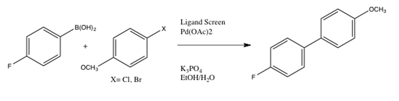
This lab introduced techniques used in the Penn/Merck High-Throughput Experimentation Center. The Suzuki-Miyaura reaction was implemented using 4 reagents, an assigned inorganic base, an assigned solvent, and pre-dosed phosphine ligands. TLC and HPLC were used to qualitatively analyze the reactivity trends of 24 reaction screens, which were all conducted under room temperature and controlled settings. The following overall reaction was conducted to catalyze sp2-sp2 carbon-carbon bonding through the use of a palladium catalyst:
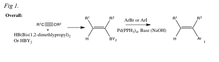
The following is a more detailed introduction to the Suzuki-Miyaura reaction, beginning with the very initial reaction conducted by Suzuki and Miyaura:
The following is an example of a reaction that could be conducted using the Suzuki-Miyaura reaction, including a more specific mechanism:
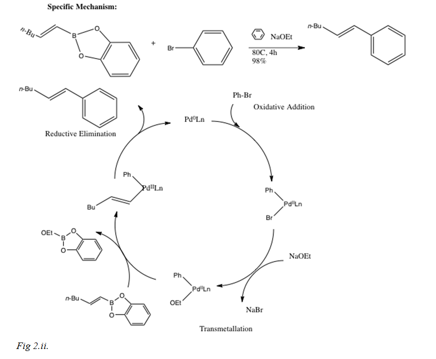
After the rate determining step of oxidative addition, where the palladium catalyst oxidizes from 0 to II and couples with the alkyl halide to produce an organopalladium complex that isomerizes from the cis to trans complex (for allylic and benzylic halides as shown previously in the two reactions), while vinyl halides retain their stereochemistry during oxidative addition. The main focus of this lab report introduction will, however, be the transmetallation step after oxidative addition.
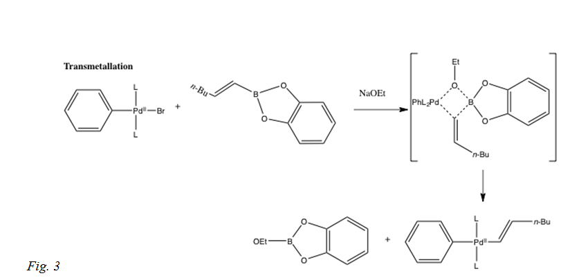
In this step of the reaction mechanism, the ligands are transferred from one location to another, from the organoboron species to the PdII complex. The exact mechanism is not completely resolved, although the base is expected to activate the organoboron compound, because organoboron compounds are very covalent and unless there is a base, the transmetalation does not occur. Boronate complexes form with a negatively charged base via quaternization of the boron as shown in Fig 3.[i]
The transmetalation mechanism is still under research, as seen in the 2011 JACS publication regarding the possible pathways for the transmetalation to occur. The two ways that could be possible is that the organoboron compound is converted to a nucleophili boronate by base and attacked by a palladium halide complex or the palladium halide is converted to a nucleophilic palladium hydroxo complex that then reacts with the neutral organoboron complex.[ii] Carrow and Hartwig show that the transmetalation is between the palladium hydroxo complex and a boronic acid, not the palladium halide complex and a trihydroxyborate. This was determined by comparing stoichiometric reaction rates between isolated species. The pathway that is correct for the transmetalation within the Suzuki Miyaura cross-coupling is the one producing the largest product of the rate constant and the largest concentration of palladium complex and boron reagent.
Other recent research aims to provide the same reaction for the desired product and basis of further research of pharmaceuticals such as anticancer gossypol and antibiotic vancomycin, without the ligands. In that case, the phosphine side reactions would not exist and the reaction could be under aerobic conditions. Kumbhar, et al discovered a way for the Suzuki-Miyaura coupling reaction to occur ligand-free with the use of zeolite immobilized palladium.[iii]
Procedure
Day one was used to assemble 24 well blocks and lid with Teflon liner, clearly labeled with initials. Obtained five 4 mL vials with caps. The reagents provided and used were Pd(OAc)2, 4-chloroanisole, 4-bromoanisole, 4-fluorophenylboronic acid; inorganic bases: potassium phosphate and sodium carbonate, phosphine ligands in 1000uL vials. 7.2mg (ended up being 9.09mg) Pd(OAc)2, a rusty orange powder, was measured carefully into 4 mL vials, carefully labeled. 60.2mg and 60.3mg respectively of the white powder 4-fluorophenylboronic acid was weighted into each of 2 vials, carefully labeled one “4-chloroanisole” and the other “4-bromoanisole”. 2.4mmoles of the selected base was weighed into the fourth vial, however, in this case the base was pre-prepared as well as the 24 reaction vials of predosed ligands and thus the reaction setup and vials were moved to the “wet box” to prepare stock solutions. To the vial with palladium acetate, 4mL of THF was added. The vial was sealed and shaken to dissolve the palladium acetate, which dissolved completely. Using 20-100 uL pipette, 25 uL of the Pd(OAc)2 solution was dosed to each 24 predosed reaction vials. The box was then transferred back to the dry box and the blowdown tool used to remove THF solvent to leave behind palladium and ligand. While the solvent was being removed, the reaction solutions were prepared. However, in this case, the solvent and base solutions were already premade (0.890 mL of selected solvent: THF, 1.8 mL of water was added to the assigned base K2CO3 for a 1.2M base solution (premade) and for the individual step, 0.890mL of THF was added to both the 4 mL vials A and B containing the 4-fluoroboronic acid. 4.90 uL of 4-Chloroanisole was added to the 4mL vial. 50 uL of 4-bromoanisole was added to the 4mL vial B. After blowdown, transferred reaction blocks back to wet box. 50uL of the 4-chloroanisole reagent solution Vial A was dosed to each of the 12 vials A1-A6 and B1-B6. 50 uL of the 4-bromoanisole reagent solution in vial B was dosed to each of the 12 vials C1-C6 and D1D6. 50 uL of the aqueous base was dosed to each of the 24 vials A1-D6. Reaction block was caped and the lid tightened with a power screwdriver, starting from the screw in the center and working in a crisscross pattern. The box was removed from the glovebox and placed on a tumble stirrer overnight until moved into the fridge in the morning to halt the reaction.
Second day was used for TLC analysis. Plate 1 consisted of (in order): A1-6, product standard, 4-chloroanisole standard, B1-6. Plate 2 consisted of (in order) C1-C6, product standard, 4-bromoanisole standard, D1-6. In 95:5 hexanes:ethylacetate mobile phase, the TLC plates were ran and the solvent line was marked. The plate results were marked and compared. The HPLC calibration curve was prepared by Dr. Rarig (tared 10 mL vial, added 8-15mg of 4,4dimethylbiphenyl, added 8-15mg of product standard, 4-fluoro-4’methoxybiphenyl, added 8mL acetonitrile to vial, capped vial and shook for dissolution, transfered 1.5-2mL of this solution to HPLC vial, injected 5uL of this sample onto HPLC, recorded area under peak for the product standard (Rf=4.78 min) and the internal standard (Rf=5.64 min)).
Samples were prepared for HPLC. Using 100-1000uL multi-channel pipette, 500 uL of prepared 0.02M solution of 4,4-dimethylbiphenyl in acetonitritle was dosed into your reaction mixture. The cap was replaced on reaction block, tightened and placed on the stirplate in order to ensure all dissolved into acetonitrile. Using the 100-1000uL multichannel, 700 uL of acetonitrile was dosed into each of 24 wells on a 96 well HPLC block. The reaction block was shared between all members of the experiment, so each quadrant was well marked. After 12-13 hours, the data took about 10min per person to extract.
Discussion
Each solvent and base applied during the experiment is extremely important as a combination for analyzing the Suzuki coupling reactions. For this experiment, the assigned solvent was THF and the assigned base was K2CO3. It was observed in literature, Wolfe and Singer, that KF was ineffective in toluene, but most efficient promoter of coupling in THF. [iv] It was hypothesized that while biphasic solvent systems generally give poor results compared to those without water and while a combination may be a poor choice, for example, K3PO4 was less compatible with THF, reaction catalyst loads can be ran at higher (boiling point of water) temperatures in toluene for better results.
After the reaction processed, the qualitative analysis consisted of two parts: TLC and HPLC. TLC plates were visualized and produced Rf values presented in the Product Characterization section. For the quantization of which lanes consumed the aryl halide starting material and which had not. Some lanes contained multiple spots (for A6, B2, C6, D1, D5), which indicated a messy reaction. In comparison between 4-chloroanisole and 4-bromoanisole, it was concluded that reactions with 4-bromoanisole reagent (C and D vials) produced far more visible reactions via TLC as well as results within HPLC, quantized by the highest P/IS value, which correleated with the basic TLC runs (C1-5 and D1-3, 5), which did not include any of the 4-chloroanisole reagent reactions. This can be used to determine that the 4-bromoanisol reagent with THF solvent and K2CO3 base produced better results.
Product Characterization
| Vial | Ligand used: | Observation: | P Value | P/IS Value |
| A1 | 1: Ataphos | Yellow |
0 |
0 |
| A2 | 2: Butyldi-1-adamantylphosphine | Milky white |
0 |
0 |
| A3 | DPPF | Yellow/orange- cloudy |
0 |
0 |
| A4 | DTBPF | Orange with percipitate |
0 |
0 |
| A5 | P(o-toluyl)3 | Peach with side precipitate |
0 |
0 |
| A6 | P(PPh3)3 | Brown-orange clear |
0 |
0 |
| B1 | P(tBu)3 HBF4 | Clear with white precipitate |
3.1407E-07 |
0.037 |
| B2 | RuPhos | Yellow with yellow precipitate |
1.07619E-05 |
1.28 |
| B3 | S-Phos | Brown |
9.11845E-06 |
1.08 |
| B4 | Xantphos | Yellow |
0 |
0 |
| B5 | X-Phos | Clear with white precipitate |
1.43179E-05 |
1.70 |
| B6 | None | Black precipitate |
0 |
0 |
| C1 | Ataphos | Orange precipitate |
1.37112E-05 |
1.63 |
| C2 | Butyldi-1-adamantylphosphine | Brown-grey precipitate |
9.48693E-06 |
1.13 |
| C3 | DPPF | Brown-red |
6.34114E-05 |
7.52 |
| C4 | DTBPF | Orange clear |
5.94021E-06 |
0.70 |
| C5 | P(o-toluyl)3 | Grey-yellow |
1.40393E-05 |
1.67 |
| C6 | P(PPh3)3 | Brown murky |
1.2474E-05 |
1.48 |
| D1 | P(tBu)3 HBF4 | Grey |
1.39598E-05 |
1.66 |
| D2 | RuPhos | Yellow-green |
1.46209E-05 |
1.73 |
| D3 | S-Phos | Yellow clear |
1.06712E-05 |
1.27 |
| D4 | Xantphos | Yellow murky |
6.70446E-06 |
0.80 |
| D5 | X-Phos | Yellow |
1.03706E-05 |
1.23 |
| D6 | None | Grey-black |
5.25868E-06 |
0.62 |
| Calibration | – | – |
7.19903E-06 |
0.85 |
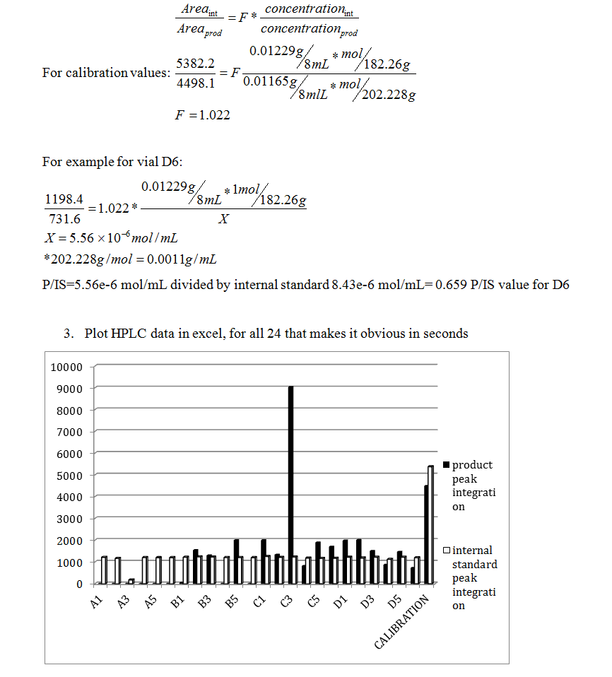
0.01165 g of recrystallized product was combined with 0.01229 g of pure 4,4′-dimethylbiphenyl (internal standard) and the mixture was dissolved in 8 mL of acetonitrile. This solution was then shot on the HPLC for analysis. These values were used for the calculation of the above P/IS values (calculation show in Question and Answer section).
Rf values from TLC- Chlorine: (solvent front: 3.15cm)
| Spotting | Rf Value |
| A1 | 0 |
| A2 | 0 |
| A3 | 0 |
| A4 | 0 |
| A5 | 0 |
| A6 | 0.79, 0.86 |
| Product | 0.60 |
| 4-Chloroanisole reagent | 0 |
| B1 | 0 |
| B2 | 0.57, 0.83 |
| B3 | 0.57 |
| B4 | 0.57 |
| B5 | 0.54 |
| B6 | 0 |
Rf values from TLC- Bromine: (solvent front: 3.10cm)
| Spotting | Rf Value |
| C1 | 0 |
| C2 | 0.48 |
| C3 | 0.45 |
| C4 | 0 |
| C5 | 0 |
| C6 | 0.48, 0.94 |
| Product | 0.45 |
| 4-Bromoanisole reagent | 0 |
| D1 | 0.13, 0.29, 0.48 |
| D2 | 0.58 |
| D3 | 0.81 |
| D4 | 0.81 |
| D5 | 0.55, 0.84 |
| D6 | 0.52 |
Upon comparison of the Rf values and HPLC data obtained for each reaction vial, the spotting values/characteristics did not match that of the HPLC integration values. Therefore, there must be cases of sources of error, especially in the TLC method. The TLC data most likely did not reflect the HPLC due to over-spotting, which occurred some of the trials. This resulted in blobs of spots in between lanes, which made the deciphering of the Rf values difficult. According to the HPLC, the first 6 runs of “A” or 4-chloroanisole reagent with THF solvent, K2CO3 base, and 1-6 ligand, had zero integration peaks or a no reaction, which was also reflected in the TLC in comparison to both the starting material and the product spot, except for A6. This A6 inconsistency may be due to a source of error, perhaps a poor cleaning of the thin TLC pipette, a over running of a side spot, or contamination of the plate. Visual observation of the product formation showed that although the HPLC confirmed zero integration peak, there was still visibly a precipitate, indicating that a visualization of the process is not enough for complete analysis of the 24 reactions. Ligand, solvent, and reagent combinations that produced high P/IS values were C1-5 and D1-3, 5.
Conclusion
According to research the use of certain types of ligands led to enhanced rate of oxidative addition while the catalytic cycle was also sped up unlike the common result of one step speeding and another slowing down. The ligands are therefore successful in their purpose of applying their electron-richness to the palladium and their bulkiness to increase the rate of reductive elimination and increase the amount of L1Pd complexes to increase the rate of transmetalation. The following experiment using the High-Throughput Experimentation Center allowed for the further understanding of screening multiple reactions within a limited amount of time, analyzing the results, and comparing the effectiveness of different solvents, ligands, and bases. Understanding each factor that contributes to the reaction process helps develop future experiment protocols and develop ideal conditions for desired reactions.
Assigned Questions
- See introduction
- Values from your calibration solution (reaction product and internal standard), calculate P/IS value that corresponds to complete conversion. Molar ratio of product to internal standard in your calibration solution? What was the relative area ratio for that sample? What is the molar ratio of theoretical product formation to our internal standard that we dosed into each reaction vial?
Molar ratio: theoretical product formation: 0.01165g/[202.228 g/mol]= molar quantity of product theoretical=5.8e-5mol. Internal standard (pure 4,4′-dimethylbiphenyl) of 0.01229g/[182.26g/mol]=6.74e-5mol internal standard.
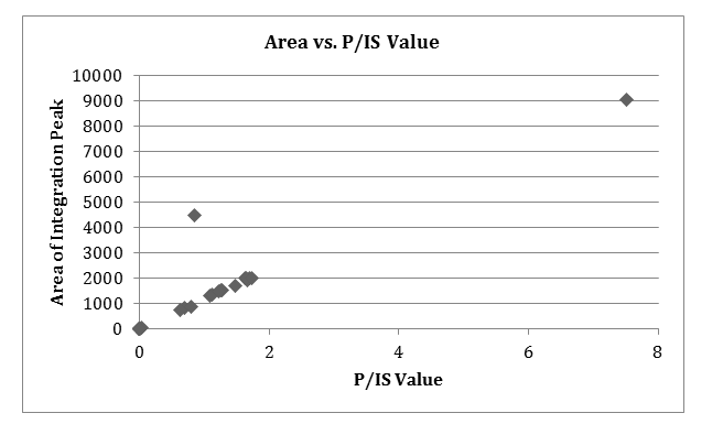
Relative area ratio: product peak integration: internal standard peak integration approximate to product: internal standard molar ratio.
 Any observed reactivity trends. Compare qualitative TLC assessment with quantitative HPLC data. What are the shortcomings of the TLC? Benefits? Short comings and benefits of HPLC?
TLC assessments are a way to observe reactivity trends. They were used to quickly assess each of the 24 reactions, which allowed the assessment to be a fast and easy way to visually compare the reactivities. However, TLC plates are also not completely reliable because the plates don’t have long stationary phases and the detection limit is high. The data obtained would just be a rough estimate and other chromatographic techniques may be used. Also, the plates were crudely placed in a beaker with solvent and the system was somewhat open, only slightly covered by aluminum foil. The many environmental factors and high likelihood of dots being overspotted, running into each other, streaking, and uneven solvent front all contribute to the shortcomings of the TLC technique.
HPLC can be run for many reactions at a fast rate and with far more accuracy. The results are easily reproducible and easy to operate. It can also be used for more complex molecules and However, these are very expensive to obtain, use, and maintain in a laboratory.
Any problems? What would you change to improve the experience?
The experience was great in the laboratory. The groups were split up well so that everyone got a section of the glovebox and took turns in a timely fashion. The calendar was poorly organized in that there were due dates that were different between the groups and I felt that I had to turn in 3 labs without getting feedback on them, which lost me a few points on technical issues.
[1] N. Miyaura and A. Suzuki, “Palladium-Catalyzed Cross- Coupling Reactions of Organoboron Compounds,” Che- mical Reviews, 1995, 95, 7, 2457-2483.
[1] Coletta, Chris, and Andrew Haidle. “The Suzuki Reaction.” Havard Chemistry 215. N.p., n.d. Web. 22 Nov. 2013. <http://www.chem.harvard.edu/groups/myers/handouts/12_Suzuki.pdf>.
[1] Carrow, Brad P., and John F. Hartwig. “Distinguishing Between Pathways for Transmetalation in Suzuki-Miyaura Reactions.” Journal of the American Chemical Society 2011, 133, 2116-119.
[1] Kumbhar, Arjun, Santosh Kamble, Anand Mane, Ratnesh Jha, and Rajashri Salunkhe. “Modified Zeolite Immobilized Palladium for Ligand-free Suzuki–Miyaura Cross-coupling Reaction.” Journal of Organometallic Chemistry 2013, 738, 29-34.Science Direct. Web. 20 Nov. 2013. <http://www.sciencedirect.com/science/article/pii/S0022328X13002325>.
[1] Wolfe, J.P.; Singer, R.A.; Yang, B.H.; Buchwald, S.L. Journal of American Chemistry Society 1999, 121, 9550-9561.
