Phosphorous Detection
In this experiment, several device designs were employed, as well as different mixtures of a combined reagent to find which of each worked best for phosphorous detection. With the final combined reagent, the 2-channel design with narrower, 2.5-mm channel widths showed the best results, and a cleaner meeting of the two solutions. This worked fine with the most concentrated 10 ppm phosphorous, and also well with the 1.3 ppm, however the more concentrated showed better results, as would be expected. Lower concentrations, for all of the designs and channel widths, were harder to detect, and some were too faint to be certain there truly was detection.
Procedure
The device designs for this experiment were made by taking a basic layout of several potential designs provided by the instructor, and modifying them to our liking using PowerPoint. Four designs were made in total, a set of two 3-channel designs along with two 2-channel designs. The Channel widths were adjusted so half of each set had 2.5-mm channels, and the other half had 3.5-mm channels. Once finalized, these designs were printed using special cellulose filter paper, and a special wax rather than ink. To ensure the wax was not only present on one side of the paper, they were heated on a hot plate to allow the wax to penetrate the paper. Each design was then tested using food coloring to make sure there was no leaking occurring.
A combined reagent was made using sulfuric acid, potassium antimonyl tartrate, ascorbic acid, and ammonium molybdate. Concentrations and volumes used are listed in Table 1 of the appendix, due to varying amounts and concentrations being employed for different combined reagents. The proper reagent was found by testing each with the 10 ppm phosphate standard, using the 2-channel device and 4 μL of each.
Once an adequate combined reagent was found, the devices were tested. In the 2-channel designs, 4 μL of both the phosphate standard and combined reagent were placed in the wells. The device was then placed, standing, in a bowl of DI water and allowed to wick until the solutions met in the top box. For the 3-channel designs, the same amounts of phosphate standard and combined reagent were placed in the first two channels, and in the third channel was placed 2 μL of ammonium molybdate. These were allowed to wick in the same way as the 2-channel designs. The phosphate standards used were 10.0, 1.3, 0.90, 0.60, 0.45, 0.30, and 0.15 ppm. Success was measured by the presence of a blue line forming at the point where the solvents met. A blank was also used to ensure the blue line was truly due to the phosphate; this was done by using DI water in place of the phosphate.
Results
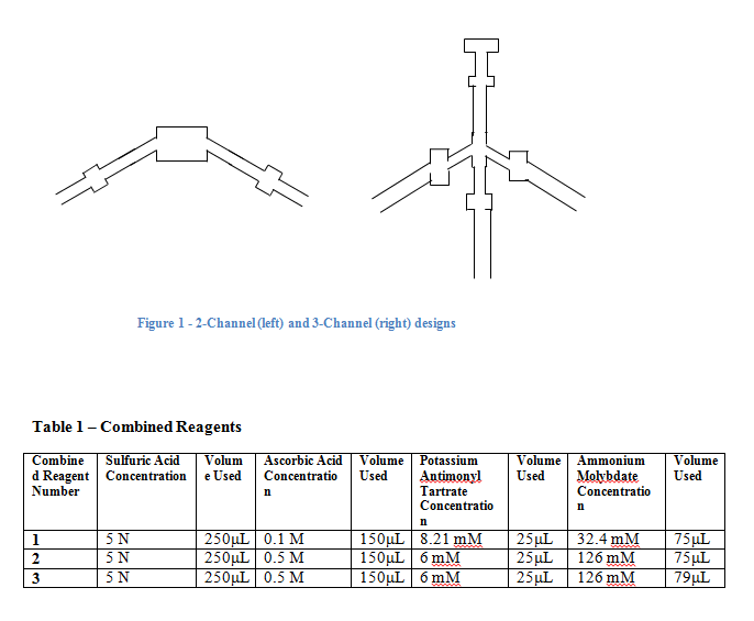
A picture of the 2- and 3-channel device designs is shown in Figure 1 of the Appendix. For the 2-channel designs, mixing was seen in the top box, very near the center in each. A thin blue line appeared right where the two solutions met, with the color being darker for a higher concentration. The 10 ppm phosphate solution showed the darkest color blue, with the shade becoming progressively lighter as the concentration decreased. However, after 0.90 ppm the line stopped appearing for this design. The width of the channel did not seem to have any effect on the actual mixing of the solutions, however the narrower columns showed faster wicking up the wells, and therefore faster mixing.
In the 3-channel designs, the mixing was observed in the top lane, usually before it actually reached the top box. A blue streak, rather than a line, was always observed on the right side of the mixing well, nearest the side of the ammonium molybdate. Again, the shade of the blue color was darkest with the highest concentration, and could be seen until 0.60 ppm, when it was very faint. The combined reagent for this design was the same as in the 2-channel, however when the additional 2 μL of ammonium molybdate met with it, this had the effect of a combined reagent with additional ammonium molybdate.
Comments
The device designs employed in this experiment seemed to have the greatest impact, after the combined reagent. When using just small amounts of reagent or standard, the well size was adequate. However, when using larger amounts, and actually for every amount used in actual experimentation, the wells could have served better had they been larger. At their current size, putting just 4 μL of solution into these wells caused the solution to saturate the paper and move away from the box in both directions. It’s unlikely, but there could have been uneven distribution of solutions in each well, with say, the phosphorous traveling nearer the water, and the combined reagent traveling closer to the mixing well. This would cause the reagent to reach the mixing well sooner, and more combined reagent would be in the mixing well as opposed to phosphorous standard.
The above problem may be remedied by using a small strip of paper in the back of the device, to keep wicking going, and keep water traveling through the top well. This was tried a few times during our experiment, but did not seem to travel very far in the strip before stopping. Also, whether the strip was used or not, there was no apparent difference in the shape and color of the mixing line, so it was not employed for most of the runs.
One obvious adaptation, after actually seeing how the devices were used, would be to have all of the channels entering the water parallel to one another, rather than at angles. For the 3-channel design, a possible change would be to have 2 channels on one side and the other opposite them, with a mixing well meeting in the middle. With this design the device could be folded, to form a sort of tripod shape so it could stand freely in the water, with the three channels meeting in the middle. This would probably eliminate the need for a specialized holder in the bowl of water.
When creating combined reagents, it was observed that when phosphorous was added to the test strip first, sometimes the mixture would turn a very dark blue, unlike what was ever seen during the actual tests. It was found that in just making the combined reagent, too high of a concentration of ammonium molybdate provided a dark blue color in the reagent itself, rather than the expected yellow-ish. The final combined reagent was made by ensuring the phosphates were the last thing added, so any blue color was due to their presence, and not a high concentration of something in the reagent.
In each run, it was apparent that a narrower channel caused the solutions to wick up into the mixing well faster. This makes sense, as there is less overall area the liquid needs to travel through. The width didn’t seem to play a large role other than simply time of travel. Had the solutions been more concentrated, they may have had more notable differences in density – thicker solutions would take longer to reach the mixing well, causing less dense solutions to reach the mixing well prematurely. Then, the wells’ widths, or their lengths, could have been adjusted so they reach the top at the same time.
References
Cissell, K. Chem 314 Lab Manual, University Center, MI, 2014
ScienceLab.com/MSDS. Accessed March 8, 2014.
Appendix