Stokes’ Law, Reynolds Number, and Measuring Liquid Viscosity
By: Colin Patrick, Trent McInturff, Michael Billups
Abstract
This report discusses the methods with which the viscosity of liquid glycerin is determined, and uses the data to validate Stokes’ Law. Two experiments were performed: the viscosity of glycerin was determined using a rotational viscometer, and the data used to validate Stokes’ Law was collected using a falling ball viscometer. Results showed that either method showed significant error and did not validate Stokes’ Law; though the revised Stokes’ Law equation gave much more accurate results for the viscosity determined from the falling ball viscometer.
Introduction
The experiments performed were an exploration of the properties of liquid glycerin and to experimentally determine its viscosity. Viscosity can be described as a fluid’s resistance to shear strain when submitted to a shear stress. High viscosity liquids will be especially prone to resisting shear stress. This idea of resistance to flow was taken a step further in the first experiment and the data collected was used to verify Stokes’ Law for a sphere falling in a liquid. In experiment #3, a falling marble was dropped in glycerin and its terminal velocity measured for use in calculating the drag force. For experiment #4, a rotational viscometer was used to find glycerin’s viscosity at laboratory room temperature. Stokes’ Law is only valid for non-turbulent flow, so Reynolds number for the falling ball viscometer was also determined.
Background and Theory
1. Stokes’ Law and Reynolds Number
Stokes’ Law is a proposition that relates the drag force experienced by a falling sphere to the sphere’s (constant) velocity in a liquid of known viscosity.
![]()
where Fd is the drag force, is the liquid viscosity, V is the (terminal) velocity, and d is the diameter of the sphere.
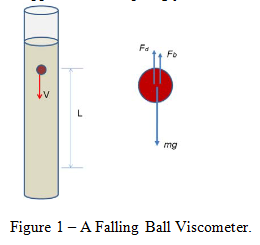
Since the sphere is falling with constant velocity there is a balance of forces that result in no acceleration.
![]()
where Fdis the drag force on the sphere, Fb is the buoyant force, and mg is the weight of the sphere (mass multiplied by the acceleration due to gravity).
This buoyant force experienced by the sphere can be described as:
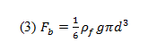
where is the buoyant force, is the liquid’s density, and d is the sphere’s diameter.
The weight of the sphere can be described as:
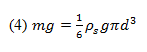
where m is the sphere’s mass, g is the acceleration due to gravity, is the sphere’s density, and d is the sphere’s diameter.
Thus, the drag force can be related by Equations 3 and 4:
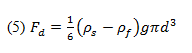
where Fd is the drag force, is the sphere’s density, is the fluid’s density, d is the sphere’s diameter, and g is the acceleration due to gravity.
By using a falling ball viscometer we can determine the sphere’s terminal velocity and also calculate the drag force using Equation 5. Stokes’ Law will be verified if the calculated drag force approximates that described in Equation 1. However, we must first determine if Stokes’ Law is applicable by finding the Reynolds number for the flow.
Stokes’ Law will suffice as a sufficient model if the flow is smooth and non-turbulent. We can determine this smoothness by calculating Reynolds number:
![]()
where Re is Reynolds number, is the fluid density, V is the characteristic velocity, d is the characteristic flow length, and is the fluid viscosity.
The uncertainty for such calculations will be determined using standard uncertainty propagation equations.
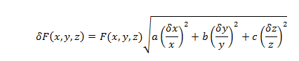
where x, y, and z are variables of a formula, a, b, and c are the exponents of the variables; , and are the uncertainty of the variables, and (x,y,z,) is the uncertainty of the value F(x,y,z).
2. Measuring Liquid Viscosity
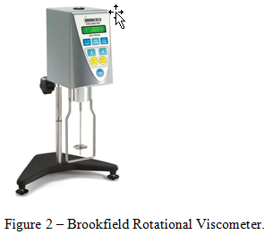
A rotational viscometer uses the principle behind the ideal model of shear stress being produced between a stationary plate and a moving one under non-slip conditions. Rather than using a moving plate, a rotational viscometer employs a rotating disc submerged into the fluid in question. This shear stress at a position r along the radius, R, of the disc can be described as:
![]()
where is the shear stress produced on both sides of the disc, is the rotational speed of the disc, r is the radius of the disc, and h is the vertical distance from the disc surface to the liquid’s free surface.
The torque produced by the shear stress induced on an element area of the disc is:
![]()
where dM is the torque on the area element, r is the disc radius, and is the shear stress.
This torque equation can be integrated and accounted for on both sides of the disc.
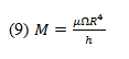
where M is the torque required for the rotational speed, is the liquid viscosity, is the rotational speed of the disc, R is the radius of the disc, and h is the vertical distance from the disc surface to the liquid’s free surface.
______________________________________________________________________________
Experiment Set-Up and Procedure
1. Stokes’ Law and Reynolds Number
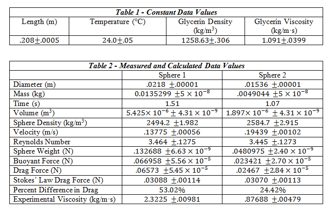
The tools required for this experiment included a set of dial calipers, 2 spheres, a Mettler-Toledo balance, a stop-watch, a meter stick, a flexible pick-up tool, and a 2L graduated cylinder filled with liquid glycerin. The temperature of the room was noted for later use in finding the tabulated values of viscosity and density of the glycerin. For each sphere, the diameter was measured using the dial calipers, and their mass found using the Mettler-Toledo balance. After filling the graduated cylinder with glycerin, the distance between two positions sufficiently far enough away from the top was measured. Using the pick-up tool and stop watch, each sphere was dropped into the liquid glycerin and the time to travel the measured distance recorded.
This distance covered divided by the time of travel gave us the approximate terminal velocity of each sphere. After using linear interpolation to find the value of the glycerin’s viscosity and density at the room temperature of 24 degrees Celsius, the values for buoyant force, drag force, Reynolds number, and the Stokes’ value for drag force were calculated using Equations 1, 3, 5 and 6. Using these values, the percent difference between the experimentally determined drag force and the drag force according to Stokes’ Law was calculated.
The Reynolds number must be determined in order for us to determine whether Stokes’ Law is even applicable to the experiment. If Reynolds number is low enough, Stokes’ Law should hold and we can validate it by comparing the drag force according to the experiment to the drag force calculated using Stokes’ Law.
By equating the experimental drag force to the theoretical Stokes’ drag force and rearranging, we were able to determine the experimental viscosity of the glycerin:
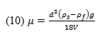
where is the experimentally determined viscosity, d is the sphere diameter, is the sphere density, is the glycerin density, g is the acceleration due to gravity, and V is the velocity.
2. Measuring Liquid Viscosity
The set-up for this experiment consisted of a rotational viscometer and the included set of spindles, as well as a beaker filled with glycerin. First, the viscometer had to be leveled, centered within the beaker, and the auto-zeroing function run to completion. A pre-determined spindle was selected and its’ number entered onto the viscometer display. The spindle was immersed in the beaker full of glycerin and then attached to the coupling nut. Next, the desired RPM was input and the full scale reading noted to ensure the rotational speed was not too high for the calibration of the machine. After letting the machine operate until steady state was reached the viscosity was recorded; multiple RPM’s were input for other trial runs. After completing 3 different trials, a second spindle was selected and the procedure repeated.
Results and Conclusion
1. Stokes’ Law and Reynolds Number
Questions
1. Are your results in agreement with Stokes’ law? List the main reasons that can cause the errors and give your explanations.
The results are not close enough to confirm Stokes’ Law. There was a human element involved in the measuring of the velocity that decreased accuracy and precision. Additionally, we had no way of knowing without the use of calculations that we were measuring terminal velocity. The marble may still have been decelerating after passing the top mark. With knowledge of the ball being at terminal velocity and using optical sensors at each mark to record time of travel, accuracy would have been much greater.
2. Do you think it is a good idea to use the average velocity of the entire period (from the instant the ball touches the liquid surface to the instant it reaches the bottom of cylinder)?
Please explain.
No, the ball must decelerate completely before terminal velocity measurements can be taken. This means the cylinder must be sufficiently long enough for this to occur.
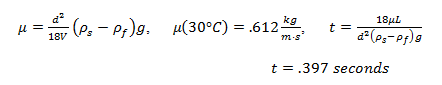
3. If you use the same marble sphere 1 to conduct the experiment at the temperature of 30°C, predict the time it takes for the marble sphere falls from 1400-ml mark to 400-ml mark, under the assumption of Stokes’ law.
2. Measuring Liquid Viscosity
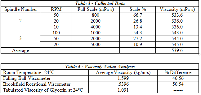
The falling ball viscometer showed slightly better accuracy at finding the glycerin’s viscosity.
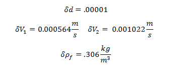
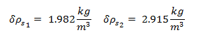
Uncertainty of Experimentally Determined Viscosity:
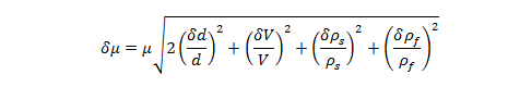
where and are the uncertainties of the viscosity , the velocity V, the diameter d, the sphere’s density , and the glycerin density , respectively.
Uncertainty of Viscosity for Sphere 1: 0.009813 kg/m·s
Uncertainty of Viscosity for Sphere 2: 0.004786 kg/m·s
Questions
1a. In the falling ball viscometer, the presence of cylinder wall will slow the motion of a falling ball when the size of ball is comparable to the cylinder diameter. Does this effect artificially increase or decrease the measured viscosity? Explain.
This increases the measured viscosity. The shear stress on the ball is proportional to viscosity times the terminal velocity divided by the distance between the ball and the cylinder wall. If the velocity is slowed due to increased shear stress induced drag on the ball brought about from the small distance between the ball and graduated cylinder, then the measured viscosity will be higher.
1b. Stokes’ law is only good for flows of very small Reynolds number Re. Suppose a better formula for drag force is:
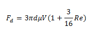
What is the calculated viscosity using this formula?
![]()
This value was much closer to the tabulated value than the original Stokes’ Law equation using the data from the falling ball viscometer, or the measurements from the rotational viscometer.
1c. How much percent difference is it compared to the viscosity derived from using Stokes’ law?
(For simplicity, you can use the viscosity obtained from the Falling Ball Viscometer to calculate the flow Reynolds number).
39.3%
2. Suppose the viscosity of fluid is out of the maximum range of a selected spindle. (a) Without changing the RPM, do you need a smaller size spindle or bigger size spindle? (b) For the same spindle, if you want to measure higher viscosity, do you use lower RPM or higher RPM?
Explain.
(a) The sensors for the rotational viscometer are sensitive and can only measure small torque values. According the equation #9, torque is directly proportional to the spindle disc radius to the fourth power. If the viscosity of a fluid is too high for a selected RPM, a smaller spindle must be used.
(b) According to equation #9, torque is directly related to rotational speed of the spindle. If the viscosity is too high for a selected spindle and RPM, the RPM must be lowered.
Conclusion
Results of this experiment show that the falling ball and rotational viscometer methods of measure the viscosity of glycerin were inaccurate. The data collected from the falling ball experiment did not verify Stokes’ Law, though it did show that the revised version of Stokes’ Law correcting for Reynolds Number was fairly accurate. This suggests that Stokes’ Law is very sensitive to flow Reynolds Number, and experimenters must account for this. Improvements in the falling ball experiment can be made to obtain more precise data for the calculation of the Stokes’ Law drag force by eliminating the human factor in measuring velocity and using optical sensors connected to a computer to calculate the time of travel and velocity of the spheres.
References
Feng, Zhi-Gang. (9/3/2012). Laboratory Exercise #3: Stokes’ Law and Reynolds Number.
Feng, Zhi-Gang. (9/6/2012). Laboratory Exercise #4: Measuring Liquid Viscosity.
Direct Industry. “DV-I Prime Rotational Viscometer.” Retrieved 10/9/13.
http://img.directindustry.com/images_di/photo-g/rotational-viscometer-13581-2508939.jpg
