Torsion Testing of Steel and Cast Iron
Introduction
To put meaning to the data and conclusions drawn in this experiment several things must be known about the materials tested and the theory behind torsion testing. The two materials tested, cast iron and mild steel, have opposing characteristics. Steel is classified as a ductile material, a ductile material is known to be able to experience very large shear forces without failing, ductile materials are also highly deformable — which helped make Pittsburgh’s steel industry world-renowned for both strength and versatility. Learn more about the rise and fall of Pittsburgh’s steel empire here.
On the other hand cast iron is a brittle material, brittle materials failure under significantly smaller shear forces than those of ductile materials, a brittle material also deforms much less under torsion.
The Tinius Olson Torsion Machine is interesting piece of equipment. It provides the extreme forces needed to understand the properties of materials. The machine basically consists of an electric motor to provide the needed torque and two circular arms. The arms have adjustable chucks to fit various sized test samples. As the chucks are tightened around the cylindrical tapered samples the motor turns just one of the arms while the other stays stationary. The machine continues to turn the sample at a continuous rate, meaning the torque applied is not constant, until the sample fails. The computers within the machine then provide us with data pertaining to each sample.
By testing the samples of steel and iron in the torsion testing machine two valuable sets of data were obtained. The first and most obvious data were the qualitative observations. From these observations you can see the different behaviors between the two materials. The second data provided, the twist angle and the torque acting on the samples, provided us with a means to graphically depict the behaviors of the materials. By graphing the twist angle against the torque, several telling properties of the materials were determined.
Procedure
For this experimentation we used two cylindrically tapered rods of cast iron and mild steel. Each was torsion tested in the Tinius Olson Torsion Machine. The following lists the steps that are need to test each material and obtain the data needed to derive several important conclusions.
- Using a ruler, measure the length of the smaller radius cylinder of each rod (Ls & Lc), not including the tapered section.
- Using a dial caliper, measure the smaller diameter of each sample (ds & dc).
- Move the arm not attached to the torsion machine away from the machine.
- Loosen the chucks in the non-attached arm and place one end of the cast iron inside the arm.
- Tighten the chucks evenly around the rod, it is very important that the rod is perpendicular to the face of the arm otherwise the data will be flawed.
- Move the non-attached arm towards the machine until the rod is inside the chucks of the attached arm.
- Tighten the chucks of the attached arm, remembering to tighten them evenly.
- Start the torsion machine.
- Observe the material as the torque is applied.
- Once the cast iron fails stop the machine.
- Pull the non-attached arm away from the machine.
- Loosen the chucks of both arms and remove the two pieces of cast iron.
- Observe the failure of the cast iron; it might be good to make a rough sketch.
- Repeat this same procedure for the steel sample.
Following this procedure several conclusion and calculations can be made pertaining to each sample.
Results
After following this procedure the torsion machine provided a set of data points containing the angle of twisting with the corresponding torque. Given this data the following plots were obtained:
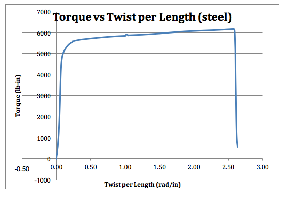
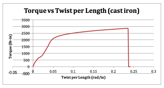
By simply comparing the two graphs to one another, the traits of each material are clearly displayed. Noticing the domain of each graph, it is shown that the steel test sample rotated nearly ten times more than the cast iron sample. Furthermore, the steel sample experienced nearly two times the torque than the cast iron. This was qualitatively observed when the experimentation took place; the lines drawn on the cast iron sample were only slightly deflected while the lines on the steel sample, originally straight, spiraled around the rod.
More information can be obtained from these graphs by analyzing the elastic portions of each material. The elastic period of each graph is defined to be the region before the material begins to have permanent deformation. By taking the slope of the torque twist (kt) lines in this region the shear modulus of each material can be determined (1). The now known modules can be used to find other properties of the materials.
To find these other properties we first create a stress- strain diagram. To do this we convert the torque data points into shear stress data points (2). We then converted the twist into shear strain (3). After doing this the shear stress can be plotted against shear strain yielding the following graphs:
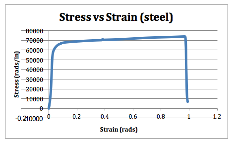
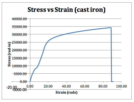
Knowing the elastic regions of each material, an educated guess is made to find the yield stress. Having found the yield stress (tys & tyc) we can also find the yield strain (gys & gyc) using the shear modulus for each metal (4). These values can be used to find the torque modulus of resiliency for the metals (5), however, since cast iron is a very brittle material, it is not resilient and has no modulus.
The graph of the shear stress and shear strain acting on the steel can be utilized yet again to determine the torque modulus of toughness. This is done by taking the area under the curve.
The graph can be used one final time to determine the limit shear strain of each metal. This strain occurs at the maximum strain, i.e. right before the metals fail (tls & tlc ).
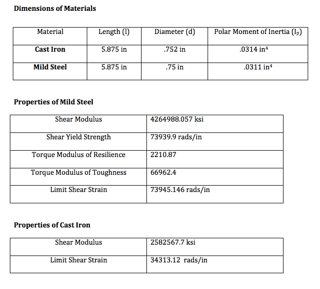
Below, are the dimensions and properties of the metals used in testing:
Dimensions of Materials
Analysis
In analyzing the results and calculated values, several assumptions can be confirmed and conclusions can be drawn. The first and most important assumption that was confirmed was the brittle tendencies of cast iron and the ductile characteristics of mild steel. This can be confirmed by analyzing the domain in which the two metals twist, that is that the steel twist nearly ten times more than cast iron. This is further confirmed by the failure surfaces of each of the samples (fig. 1 & fig. 2). The flat failure surface of the steel shows that the steel failed due to shear, while the angled failure surface of the cast iron shows that the cast iron failed due to maximum-tensile-stress. These failures are typical failures for ductile and brittle materials. The data also show how steel failed at much larger strain than that of cast iron nearly two times larger, this confirms the assumption that cast iron would fail under smaller strains.
We can understand the nature of steel even further by looking at the two modules. The large modulus of resilience of steel puts a number to the qualitative observation of the twisted steel. It makes sense that the still was able to twist so much if it is in fact resilient. The modulus of toughness explains why the steel was capable of experiencing higher strain that that of cast iron.
Though the results in the experiment may confirm what was expected from the experimentation, in comparing the derived properties of the materials to the known properties of the materials there are some conflictions. Neither of the shear modulus agrees with the accepted values, this error can most likely be attributed to not choosing the correct domain for the elastic region of each material. For the cast iron there is extreme discrepancy with the accepted value, in our experimentation the cast iron was put in the torsion arms tight enough so the iron effectively went through two different tests and only the data from the second test was used, this most likely caused problems. The majority of error though is most likely due to incorrect units, not knowing the SI units for the modules and various parameters led me to revise my calculations several times. To go about preventing these errors would be easy, by simply familiarizing myself with terms and the machinery prior to the experimentation and write up would make things a lot more seamless and easy.
Though there was a large amount of error in this experiment a lot was learned about torsion testing. Torsion testing can provided the characteristics of materials similar to tension testing. By understanding properties of a material and how they fail, i.e. steel failing under tensile stress, allows one to understand how a material should be used. A material like steel is a very suitable for lots of most movement due to its resilient nature, so it would be perfect to build structures with in an earthquake prone area. Knowing these properties provides valuable insist into the design process of civil engineers.
