Synthesis of Trinuclear Metal-Carboxylate Clusters via Ligand Exchange
Written by Jessica Weaver
Trinuclear metal carboxylate clusters of the general formula M3O(O2CR)6+ (where M= Fe (III), Cr (III), V (III); R=CH3 or C6H5) capped with monofunctionalized carboxylates were studied for their potential use as molecular building blocks, or secondary building units (SBUs), in the rational synthesis of metal organic frameworks (MOFs). Clusters were synthesized and characterized using single-crystal X-ray diffraction, powder X-ray diffraction (PXRD), and attenuated total reflectance spectroscopy (ATR-IR). Ligand exchange reactions were performed under various reaction temperatures, metal:ligand ratios, and solvent systems. Fe-, Cr-, and V- containing clusters can be synthesized in sufficient yields and purity for subsequent ligand exchange experiments. Ligand exchange on the surfaces of trinuclear SBU clusters may have been demonstrated for the first time, suggesting that these clusters may be robust candidates for the rational synthesis of metal organic frameworks.
There are many gas separations crucial to industry and the environment that are energetically unfavorable, such as the separation of olefins from paraffins, O2 from N2, and CO2 from flue gas or air [1]-[5]. In many instances industrial cryogenic distillation is used, a process of condensing gas mixtures to liquids within columns requiring high pressures and low temperatures [6]. Therefore, materials that can physically and selectively adsorb gas molecules at temperatures near or higher than room temperature can considerably reduce the energetic costs associated with standard industrial procedures [7], [8].There are many types of porous adsorbent materials, such as activated carbon, silica, zeolites, and carbon-based molecular sieves as well as polymeric membranes synthesized from glassy or rubbery polymers [1]-[5], [9], [10]; however, none of these materials offer the chemical tunability and facile modular synthesis associated with a newly discovered class of hybrid organic/inorganic materials known as metal organic frameworks (MOFs) [11]. These framework materials are constructed by metal-ions or metal-ion clusters, known as secondary building units (SBUs) that are interlinked by organic ligands to form 1-, 2- and 3-D frameworks [12]. Many MOFs have revealed high internal surface areas allowing them to adsorb significant amounts of gas on the framework surface. Furthermore, by careful selection of the ligand and metal, which control pore size/shape and specific surface interactions with guest species, MOF properties can be tuned for specific functions.MOF-driven gas separations require a gas mixture to pass through a column packed with a MOF material, with the more strongly adsorbed gas component remaining trapped in the frameworks while the weakly adsorbed components are removed [11]. In 2009, the first MOF membranes with micrometer thicknesses were synthesized and successfully applied to H2/CO2 and H2/CH4 separations, with commercially competitive selectivities of ~10 [13]. As of today, an estimated 70 sorbent-like MOFs are known to selectively adsorb components of gaseous mixtures [4], [7], [14]. According to Web of Knowledge, as of June 2013 approximately 16,000 publications contained the phrase “metal organic frameworks” [15].In the past, new porous frameworks have been discovered using crude, investigative methods that rely on various combinations of metal salts and organic acids all while varying reaction conditions [16]. It is currently unknown whether MOF formation is based upon the addition of single metal-ions or the addition of larger metal-oxide constituents that first form in solution; as a result, there is little predictability in the crystal structures that might form. Instead, a new rational design approach called reticular synthesis [17] can be taken towards MOF formation. Multi-atom molecular, metal-oxide clusters (SBUs) that are capped with monofunctionalized carboxylate ligands can be used in place of metal salts. Through a ligand exchange process on the surface of the SBU with a difunctionalized (or trifunctionalized) carboxylate, framework formation can be achieved. These SBUs intrinsically possess geometries that limit the structural degrees of freedom of a growing crystal and are rigid because of multiatom vertices. Additionally, the high bond dissociation energies of M-O-C bonds are ideal for SBU synthesis, and ultimately, the synthesis of MOFs that are stable and robust. Further preselected building blocks can be used in order to build frameworks that have predefined structural features and hence properties [12], [16], [17].
Before the reticular synthesis approach can be applied to the design of macromolecular networks such as MOFs, ligand exchange must be experimentally demonstrated on the surface of SBUs. The model SBU presented in this work is the trinuclear molecular cluster of the general formula M3O(O2CR)6+ (where M = metal = Fe (III), Cr (III), V (III); R = CH3 or C6H5) capped with monofunctionalized carboxylates (Figure 1). Depending on reaction conditions such as temperature, solvent, metal:ligand ratio, and ligand pKa, the capping ligands are exchanged with other monofunctionalized ligands (bi- and tri-carboxylates). For the first time, the reaction conditions that initiate and complete ligand exchange within trinuclear metal clusters are reported. Ultimately, with knowledge of such reaction conditions, MOF synthesis via an exchange of monofunctionalized carboxylates can help systematically exhaust all possible MOF structures constructed from a few molecular building blocks.
Materials and Methods
Chemicals and Reagents.
The following reagents were used: Cr(NO3)3∙9H2O (98.5%, Alfa Aesar), VCl3 (95%, Strem Chemicals, Inc.), Fe(NO3)3∙9H2O (98%, Sigma-Aldrich), Mn(O2C2H3)2∙4H2O (99%, Acrōs Organics), Co(O2C2H3)2∙4H2O (98%, Alfa Aesar), and Pb(O2C2H3)2∙3H2O (99%, Alfa Aesar). Clusters were synthesized in various solvents: methanol (MeOH), diethyl ether, deionized H2O, acetic acid (CH3COOH), pyridine (C5H5N), or sodium acetate (NaCH3COO) solution (solvent grade, Sigma Aldrich). Crystals were washed with diethyl ether or deionized H2O. Ligand exchange reactions were carried out in MeOH, DMF, deionized H2O and ACN. Solvents were used without further purification.
Synthesis Procedures.
If required, synthesis reactions were performed using standard Schlenk line techniques under N2 atmosphere. Generally, stoichiometric amounts of the metal salt and the monodentate carboxylate ligand were combined in solution and stirred under reflux at 45-60°C. Final solutions were allowed to cool to room temperature and were filtered to remove precipitated salts. Evaporation of solutions yielded dry powders that were then dissolved in minimal amounts of solvent. Crystals were grown from final solutions at room temperature after an average of 2-3 days.
Chromium (III) Carboxylate Clusters.
The synthesis of [Cr3O(C7H5O2)6(MeOH)3](NO3)∙2MeOH was previously reported [18]; however, an additional procedure utilizing half the original molar amount of MeOH also yielded crystals. For the attempted synthesis of [Cr3O(C2H3O2)6(MeOH)3](NO3)∙2MeOH, the original procedure [18] was followed except for the following modifications. After stirring a solution of 0.5048 g (1.26 mmol) Cr(NO3)3∙9H2O and 15 ml MeOH under reflux for 10 minutes, 2.52 mmol of NaO2C2H3 was added to the solution instead of 2.52 mmol of NaO2CPh. The synthesis of [Cr3O(O2C2H3)6(H2O)3](O2C2H3)∙xH2O was previously reported [19] and modified for a smaller scale synthesis. Instead of using 80.0 g of Cr(NO3)3∙9H2O, 1.0 g was used and all other amounts of reagents were scaled down accordingly to maintain the correct stoichiometric ratios.
Vanadium (III) Carboxylate Clusters.
The syntheses of [V3(μ-O)(μ- C2H3O2)6(OH2)3]Cl, [V4(μ-OH)4(μ-C2H3O2)4(OH2)8]Cl4, and [V3O(O2C2H3)6(py)3](ClO4) were previously reported [20]. The synthesis of [V3O(O2CPh)6(OH2)3]Cl was derived from a chromium (III) carboxylate synthesis [18]: 0.1999 g (1.26 mmol) of VCl3 was added to 15 ml warm MeOH instead of 0.5043 g (1.26 mmol) of Cr(NO3)3∙9H2O.
Iron (III) Carboxylate Clusters.
The syntheses of [Fe3O(C2H3O2)6(OH)2](NO3)∙5H2O and [Fe3O(C7H5O2)6(H2O)3](NO3) were previously reported [21].
Mixed Trivalent Metal Clusters.
The synthesis of CoMn2(O)(C2H3O2)6(py)3 was previously reported [22]; however, 4.2 ml of acetic acid (98%, Sigma-Aldrich) was used instead of 4.2 ml of glacial acetic acid.
Ligand Exchange Procedures.
Generally, for reactions at temperatures below 110°C, stoichiometric amounts of one cluster type, one ligand, and one solvent mixture were added to a 20-mL glass reaction vial and closed tightly with a Teflon cap. At temperature above 110°C, a reaction bomb was used. Vials were heated in a reaction oven at constant temperature for no longer than 1 day and cooled to room temperature. Any crystalline products were characterized using XRD and/or ATR-IR.
Characterization Methods.
Powder X-ray Diffraction.
Powder X-ray diffraction patterns were collected using a Bruker AXS D8 Discover instrument equipped with a GADDS detector or a Bruker D8 Advance Powder X-ray diffractometer with Cu Kradiation. Samples were placed onto a Si substrate and pushed flat with a glass cover slip. Data was collected from approximately 5 to 65° in 2 and then compared to powder patterns that were calculated using crystallographic information files (CIFs) either obtained from the Cambridge Crystal Structure Database or generated from single crystal structure solutions carried out at the Molecular Foundry. Powder X-ray diffraction patterns were used to determine the purity of reaction products and identify crystal phases.
Single-crystal X-ray Diffraction.
Single crystals were first placed in immersion oil and then mounted on a loop with a small amount of vacuum grease. Data was collected using a Bruker D8 Venture diffractometer using either Mo or Cu Kradiation at temperatures ranging from room temperature to 150 K using a N2 cryostream.
Infrared Spectroscopy.
IR measurements were carried out using a Perkin Elmer Spectrum One FT-IR with ATR (attenuated total reflectance) assembly. For data collection, powder samples were placed on a ZnSe plate and pushed flat on the ATR assembly with a stainless steel disk and a force gauge. Spectra were then collected from 600-4000 cm-1 and used to identify vibrational modes associated with specific functional groups within the as-synthesized clusters.
Results
Microscope images of [Cr3O(C7H5O2)6(MeOH)3](NO3)∙2MeOH and [V4(μ-OH)4(μ- OOC2H3)4(OH2)8]Cl4 show little to no solvent or unreacted starting materials, suggesting that the collected crystals are of high purity (Figure 2b and 6b). In order to quantify the purity of the crystals, crystal structures of trinuclear and tetranuclear metal-carboxylate clusters previously described in [18]-[22] were determined using single-crystal and powder XRD. A comparison between the calculated PXRD pattern of [Cr3O(C7H5O2)6(MeOH)3](NO3)∙2MeOH obtained from the Cambridge Crystallographic Data Center (CCDC) and experimental PXRD patterns shows the alignment of prominent 2θ peaks (Figure 2). Similar peak alignments for the first and last filtrates suggest that few impurities precipitate from solution as multiple filtrates are collected. Additionally, an ATR-IR spectrum of [Cr3O(C7H5O2)6(MeOH)3](NO3)∙2MeOH shows characteristic bands at 1570 and 1423 cm-1 (sharp), due to υas (COO) and υs (COO) stretching modes; 1393 cm-1 (broad) due to nitrate ions in the complex, and 663 cm-1 (sharp) due to the υas (Cr3O) vibrational mode [18]. Figures 3-6 and 8 demonstrate a similar analysis of crystal purity using XRD and ATR-IR methods for the following clusters: [Fe3O(O2C2H3)6(OH)2]NO3∙5H2O, Fe3O(O2C7H5)6(H2O)3](NO3), [V3(O)( O2C2H3)6(OH2)3]Cl, and [V4(OH)4(O2C2H3)4(OH2)8]Cl4, the last of which can be isolated in purely the P42/mnm or the I42m crystal phase [20]. The above synthesis procedures were also modified in an attempt to synthesize V- or Cr-containing clusters with alternative ligands; however, none of these reactions resulted in crystalline or powder products. Rather, recrystallization attempts produced viscous films.
Next, the as-synthesized, pure crystals of [Cr3O(C7H5O2)6(MeOH)3](NO3)∙2MeOH, [Fe3O(O2C2H3)6(OH)2]NO3∙5H2O, Fe3O(O2C7H5)6(H2O)3](NO3), and [V3(O)(O2C2H3)6(OH2)3]Cl were mixed with sodium acetate or sodium benzoate in various solvents in an attempt to exchange ligands on cluster surfaces. Tables 1-4 report the reaction conditions for all ligand exchange processes discussed in this paper.
Discussion and Conclusion
Of the attempted ligand exchange reactions summarized in Tables 1-4, only reactions with the [Fe3O(O2C2H3)6(OH)2]NO3∙5H2O cluster and the sodium benzoate ligand yielded light orange crystallites. Initially, a reaction with 10 mg of starting cluster yielded thin, light orange crystals dispersed in excess benzoate ligand (Figure 7a). A second reaction with 15 mg of starting cluster yielded two phases of orange crystals: the first phase, red-orange plates, were similar in color to [Fe3O(O2C2H3)6(OH)2]NO3∙5H2O starting material (Figure 7b) while the second phase, light-orange columns, resembled Fe3O(O2C7H5)6(H2O)3](NO3). Comparisons between ATR-IR spectra of the ligand exchange product, [Fe3O(C7H5O2)6(H2O)3](NO3), and [Fe3O(C2H3O2)6(OH2)](NO3)∙5H2O (Figure 8) show clear peak shifts corresponding to known carboxyl group vibrational modes, suggesting that the acetate ligands of the original cluster have been perturbed. However, these results are only preliminary and not sufficient as definitive proof of ligand exchange.
In future studies, it will be crucial to determine the crystal structures of exchange products using PXRD, single-crystal XRD, and mass spectrometry in the presence of excess ligand. Additionally, the precise reaction conditions that lead to complete ligand exchange, rather than partial ligand exchange, will need to be determined if SBUs can be used as precursors to metal organic frameworks. Finally, if trinuclear and tetranuclear metal-carboxylate clusters are to be used in MOF synthesis, they must not decompose as they become incorporated into complex frameworks or linked via multidentate ligands. Nonetheless, our results represent the first steps towards proving the ligand exchange process on the surface of robust SBUs.
Acknowledgments
JAW conducted her research at the Inorganic Division of the Molecular Foundry at Lawrence Berkeley National Laboratory from June to August 2013. She thanks Jason Lee for help with single crystal structure characterization and José Primera-Pedrozo for help with ligand exchange experiments. Finally, she thanks Dr. Joshua Schrier and Dr. Casey Londergan of Haverford College, both of whom encouraged her to apply for the internship. This work was supported in part by the U.S. Department of Energy, Office of Science, Office of Workforce Development for Teachers and Scientists (WDTS) under the Science Undergraduate Laboratory Internship (SULI) program.
References
[1] E. S. Kikkinides and R. T. Yang, “CONCENTRATION AND RECOVERY OF CO2 FROM FLUE-GAS BY PRESSURE SWING ADSORPTION,” Industrial & Engineering Chemistry Research, vol. 33, pp. 2881-2881, Nov 1994.
[2] D. Ko, R. Siriwardane, and L. T. Biegler, “Optimization of pressure swing adsorption and fractionated vacuum pressure swing adsorption processes for CO2 capture,” Industrial & Engineering Chemistry Research, vol. 44, pp. 8084-8094, Oct 12 2005.
[3] M. T. Ho, G. W. Allinson, and D. E. Wiley, “Reducing the cost of CO2 capture from flue gases using pressure swing adsorption,” Industrial & Engineering Chemistry Research, vol. 47, pp. 4883-4890, Jul 16 2008.
[4] P. Bernardo, E. Drioli, and G. Golemme, “Membrane Gas Separation: A Review/State of the Art,” Industrial & Engineering Chemistry Research, vol. 48, pp. 4638-4663, May 20 2009.
[5] Z. Yong, V. Mata, and A. E. Rodrigues, “Adsorption of carbon dioxide at high temperature – a review,” Separation and Purification Technology, vol. 26, pp. 195-205, Mar 1 2002.
[6] D. J. Safarik and R. B. Eldridge, “Olefin/paraffin separations by reactive absorption: A review,” Industrial & Engineering Chemistry Research, vol. 37, pp. 2571-2581, Jul 1998.
[7] J. Wilcox, Carbon Capture. New York: Springer, 2012.
[8] R. W. Baker, “Future directions of membrane gas separation technology,” Industrial & Engineering Chemistry Research, vol. 41, pp. 1393-1411, Mar 20 2002.
[9] R. W. Baker, Membrane Technology and Applications, 3 ed. United Kingdom: John Wiley and Sons Ltd, 2012.
[10] P. M. Budd and N. B. McKeown, “Highly permeable polymers for gas separation membranes,” Polymer Chemistry, vol. 1, pp. 63-68, Mar 2010.
[11] D. M. D’Alessandro, B. Smit, and J. R. Long, “Carbon Dioxide Capture: Prospects for New Materials,” Angewandte Chemie-International Edition, vol. 49, pp. 6058-6082, 2010 2010.
[12] M. Eddaoudi, D. B. Moler, H. L. Li, B. L. Chen, T. M. Reineke, M. O’Keeffe, et al., “Modular chemistry: Secondary building units as a basis for the design of highly porous and robust metal- organic carboxylate frameworks,” Accounts of Chemical Research, vol. 34, pp. 319-330, Apr 2001.
[13] J. Gascon and F. Kapteijn, “Metal-Organic Framework Membranes-High Potential, Bright Future?,” Angewandte Chemie-International Edition, vol. 49, pp. 1530-1532, 2010 2010.
[14] J.-R. Li, R. J. Kuppler, and H.-C. Zhou, “Selective gas adsorption and separation in metal-organic frameworks,” Chemical Society Reviews, vol. 38, pp. 1477-1504, 2009 2009.
[15] Web of Knowledge [Online].
[16] D. J. Tranchemontagne, J. L. Mendoza-Cortes, M. O’Keeffe, and O. M. Yaghi, “Secondary building units, nets and bonding in the chemistry of metal-organic frameworks,” Chemical Society Reviews, vol. 38, pp. 1257-1283, 2009 2009.
[17] O. M. Yaghi, M. O’Keeffe, N. W. Ockwig, H. K. Chae, M. Eddaoudi, and J. Kim, “Reticular synthesis and the design of new materials,” Nature, vol. 423, pp. 705-714, Jun 12 2003.
[18] A. Vlachos, V. Psycharis, C. P. Raptopoulou, N. Lalioti, Y. Sanakis, G. Diamantopoulos, et al., “A nearly symmetric trinuclear chromium(III) oxo carboxylate assembly: preparation, molecular and crystal structure, and magnetic properties of Cr3O(O2CPh)(6)(MeOH)(3) (NO3) center dot 2MeOH,” Inorganica Chimica Acta, vol. 357, pp. 3162-3172, Aug 5 2004.
[19] M. K. Johnson, D. B. Powell, and R. D. Cannon, “VIBRATIONAL-SPECTRA OF CARBOXYLATO COMPLEXES .3. TRINUCLEAR BASIC ACETATES AND FORMATES OF CHROMIUM(III), IRON(III) AND OTHER TRANSITION-METALS,” Spectrochimica Acta Part a-Molecular and Biomolecular Spectroscopy, vol. 37, pp. 995-1006, 1981 1981.
[20] F. H. Fry, B. A. Dougan, N. McCann, C. J. Ziegler, and N. E. Brasch, “Characterization of novel vanadium(III)/acetate clusters formed in aqueous solution,” Inorganic Chemistry, vol. 44, pp. 5197-5199, Jul 25 2005.
12
[21] J. F. Duncan, C. F. Kanekar, and K. F. Mok, “Some Trinuclear Iron (III) Carboxylate Complexes,” J. Chem. Soc. (A), pp. 480-482, 1969.
[22] D. Srinivas, S. A. Chavan, and P. Ratnasamy, “Preparation of adipic acid, e.g. used for manufacture of plasticizer, involves oxidizing cyclic compound in polar solvent with oxygen and cobalt-manganese cluster complex catalyst and oxidation initiator at preset temperature and pressure,” US6521789-B1; EP1325901-A1; EP1325901-B1; DE60207677-E; ES2254536-T3.
Figures and Tables
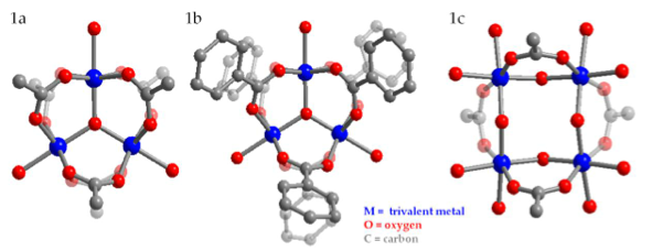
Figure 1. The fundamental structures of metal-carboxylate SBUs are represented by ball-and- stick molecular models. M= trivalent metal (Cr (III), V (III), or Fe (III)); O = oxygen; C = carbon. A trinuclear cluster with acetate ligands (left), a trinuclear cluster with benzoate ligands (middle), and a tetranuclear cluster with acetate ligands (right). 
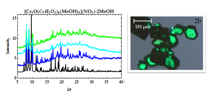
Figure 2. PXRD patterns of [Cr3O(C7H5O2)6(MeOH)3](NO3)∙2MeOH (2a): calculated from CCDC (black), 1st filtrate (dark blue), 4th filtrate (light blue), and 5th filtrate. Microscope image (2b) of [Cr3O(C7H5O2)6(MeOH)3](NO3)∙2MeOH.
15
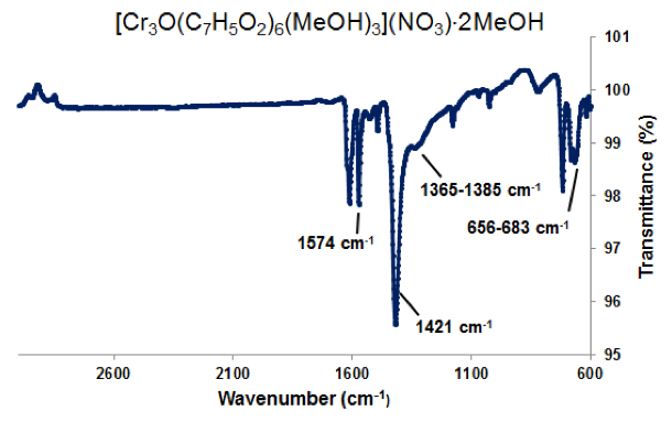
Figure 3. ATR-IR of [Cr3O(C7H5O2)6(MeOH)3](NO3)∙2MeOH. Selected peaks: 1574 cm-1 (sharp) is νas(COO), 1423 cm-1 (sharp) is νs(COO), 1365-1385 cm-1 (broad) is ionic nitrate within the complex, and 656-683 cm-1 is νas(Cr3O).
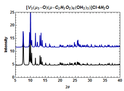
Figure 4. PXRD patterns of [V3(μ3-O)(μ-C2H3O2)6(OH2)3]Cl•4H2O. The calculated pattern from the CCDC (black) and the pattern obtained from single-crystal XRD (dark blue).
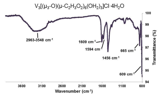
Figure 5. ATR-IR of [V3(μ3-O)(μ-C2H3O2)6(OH2)3]Cl•4H2O. Selected peaks: 2963-3548 cm-1 (broad), 1609 cm-1 (sharp), 1594 cm-1 (medium), 1456 cm-1 (sharp), 665 cm-1 (medium), 609 cm-1 (medium).
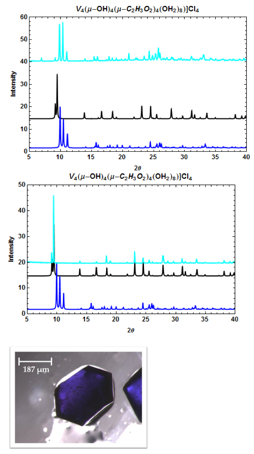
Figure 6. PXRD patterns of [V4(μ-OH)4(μ-C2H3O2)4(OH2)8]Cl4 (top, middle) and a microscope image of one crystal (bottom). The calculated patterns from the CCDC (dark blue = I-42m space group; black = P4(2)/mnm space group) and the pattern obtained from experiment (light blue). The two crystal phases can be separately recrystallized.
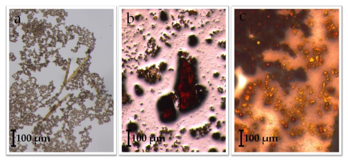
Figure 7. Observed crystallites of an attempted iron acetateiron benzoate ligand exchange reaction with a 2:1 ACN:H2O solvent system. Part (a) shows light orange, columnar crystals dispersed within excess ligand. From another reaction: (b), which may be unreacted [Fe3O(C2H3O2)6(OH)2](NO3)∙5H2O, and (c), which is an unidentified reaction product.
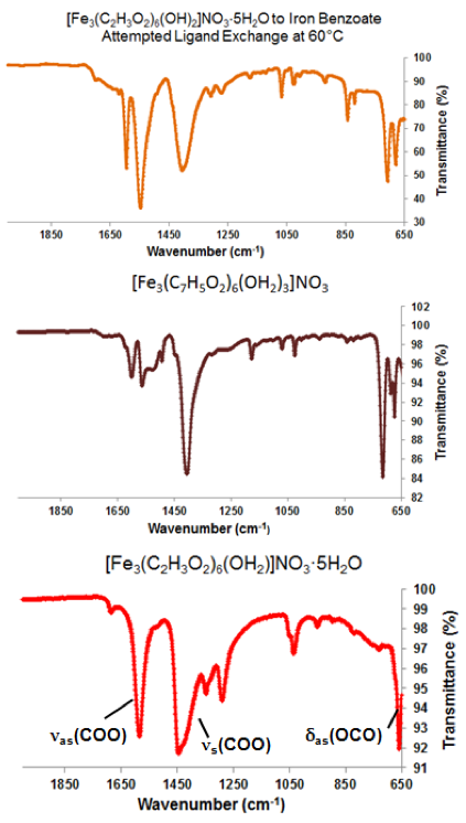
Figure 8. Comparisons between ATR-IR spectra of a ligand exchange product (top), [Fe3O(C7H5O2)6(H2O)3](NO3) (middle), and [Fe3O(C2H3O2)6(OH2)](NO3)∙5H2O (bottom). Vibrational modes of known shifted carboxyl group stretches are labeled.
[Cr3O(O2C7H5)6(MeOH)3](NO3)∙2MeOH —->
[Cr3O(C2H3O2)6(MeOH)3](NO3)∙2MeOH at 60°C 22
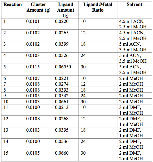
Table 1. [Cr3O(O2C7H5)6(MeOH)3](NO3)∙2MeOH —-> [Cr3O(C2H3O2)6(MeOH)3](NO3)∙2MeOH attempted ligand exchange at 60°C. Acetate ligand was added via sodium acetate. Reactions were done in 20-ml vials and heated for 1 day.
[V3O(μ3-O)(μ-C2H3O2)6(OH2)3]Cl —–>
[V3O(μ3-O)(μ-C7H5O2)6(OH2)3]Cl at 60°C
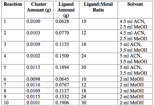
Table 2. [V3O(μ3-O)(μ-C2H3O2)6(OH2)3]Cl[V3O(μ3-O)(μ-C7H5O2)6(OH2)3]Cl attempted ligand exchange at 60°C. Acetate ligand was added via sodium acetate. Reactions were done in 20-ml vials and heated for 5 hrs.
[Fe3O(C2H3O2)6(OH)2](NO3)∙5H2O —–>
[Fe3O(O2C7H5)6(OH)2](NO3)∙5H2O at Room Temperature 24 
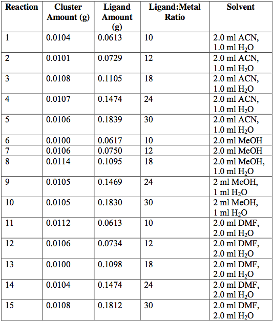
Table 3. [Fe3O(C2H3O2)6(OH)2](NO3)∙5H2O [Fe3O(O2C7H5)6(OH)2](NO3)∙5H2O attempted ligand exchange at room temperature. Acetate ligand was added via sodium acetate. Reactions were done in 20-ml vials and heated for 1 day.
[Fe3O(C2H3O2)6(OH)2](NO3)∙5H2O —->
[Fe3O(O2C7H5)6(OH)2](NO3)∙5H2O at 60°C
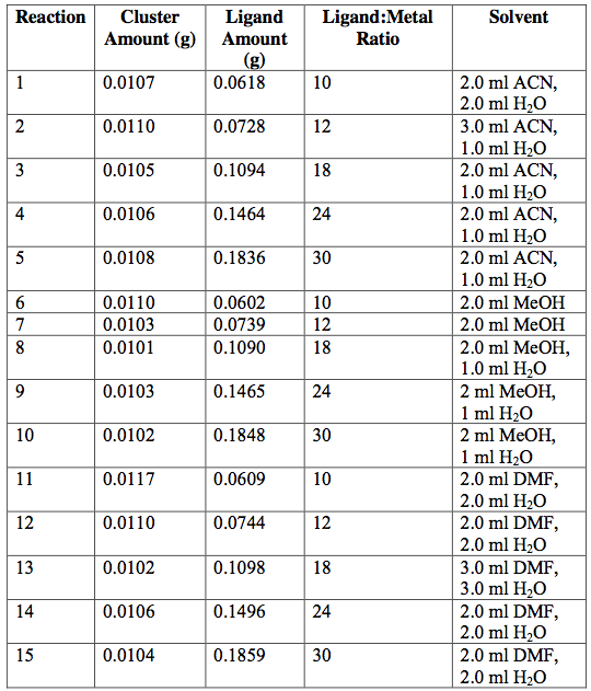
Table 4. [Fe3O(C2H3O2)6(OH)2](NO3)∙5H2O [Fe3O(O2C7H5)6(OH)2](NO3)∙5H2O attempted ligand exchange at 60°C. Acetate ligand was added via sodium acetate. Reactions were done in 20-ml vials and heated for 1 day.
