Centripetal Force Experiment
Centripetal Force
By: Alexander Jones
Abstract
In this experiment Newton’s first and second laws of motion were used to study and verify the expression for the force, F, to be provided to mass, m, to execute circular motion. Two experimental conditions were measured using 1) a simple pendulum and 2) a rotating table. To acquire data regarding force, period, and velocity of the experimental setups a force sensor and photogate motion sensor were employed. The data was then analyzed graphically and mathematical calculations were performed on the graphical data. Tension of the pendulum and centripetal force on the rotating table were calculated using formulae derived from Newton’s first and second law, angular acceleration and angular velocity. The percentage difference for the calculated tension of the pendulum string and the actual tension is .5% whereas the difference in the calculated centripetal force was 18% different. The results of the experiment confirm that the tension caused on the string of the pendulum is the centripetal force in addition to the force due to gravity. The large percent difference in the second experiment is due to an error in the experimental procedure.
Experimental Theory
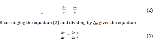
Newton’s laws are used to describe patterns of motion on masses. The first law states that a body remains in constant uniform motion, or at rest, unless a net force acts upon it. [1] The second law states that a body’s force is equal to its mass times its acceleration. Acceleration, being a quantity calculated by how fast the velocity is changing per unit time, can be expressed as the derivative of velocity giving the equation:

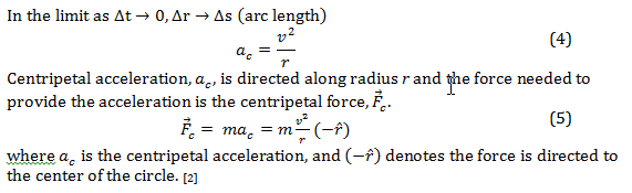
Applying a force parallel to the direction of motion will cause the velocity to either increase or decrease in magnitude, whereas a force applied to any angle will cause a change in magnitude and direction. On the contrary, a force applied perpendicular to the direction of motion will only cause a change in the direction, not magnitude. Thusly, if a force is kept constant perpendicular to the direction of motion then uniform motion along an arc with radius r is achieved. Applying this force constantly to the direction of motion will cause the body to remain moving in a uniform circular motion. [1]
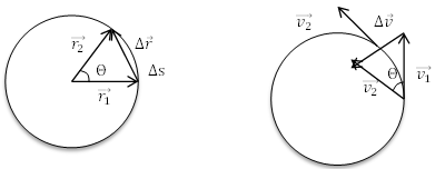
Figure I: Showing the similar triangles made by the velocities of equal magnitude compared to the triangle made by radii separated by angle Θ. Triangles a and b are similar in that they create isosceles triangles with angle Θ, and have equal side lengths. [1] [2]
In Figure Ia. radii and are separated by angle Θ and in the limit as Using velocities from figure Ib. and , with them being equal in magnitude, and placing the tail of to the head of to get the change in velocity, Δ. The two triangles are similar in that (Δr) (Δv) and therefore it is also true that
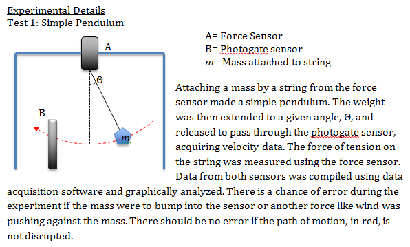
 A mass, m, attached to a string and set into motion by pulling to angle Θ creates the experimental conditions for a simple pendulum, as shown in Figure II. The only two external forces on the mass are the force due to gravity, –mg, and the force of tension on the string, .
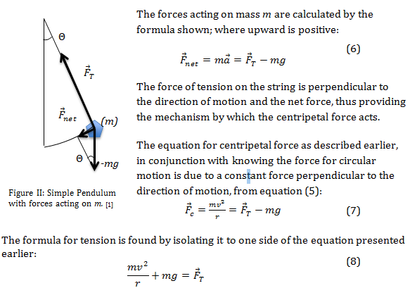
The formula for tension is found by isolating it to one side of the equation presented earlier:

When the force of gravity is counteracted, possibly by a horizontal spinning table, then the force of tension on the string is only due to the centripetal force and the second term is equal to 0. Linear velocity is kept constant in order to maintain a similarly constant angular velocity and can be written in terms of radians where T is the period:

Since the centripetal force is mass times velocity squared over the radius of the circle the two formulae, (5) and (9), can be combined:

Results and Discussion:
Test 1: Simple Pendulum
The measurements taken from Test 1 were recorded and placed onto graph 1. The velocity and force were measured from 16-25 seconds, as shown in graph 1, to obtain the mean values.
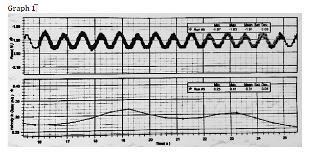 Graph 1 shows the data for Force/Time on top and Velocity/Time on the bottom from 16-25 seconds, the time over which the mean values for velocity and force were calculated using the data acquisition software.
The mean value for velocity is .31 m/s and the mean value for force is 1.91N. The mean value for velocity will be used in equation (8) to calculate the force of tension that should be exhibited by the string. Radius of the pendulum, r= .45m — Mass of weight on string, m= .200kg
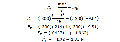
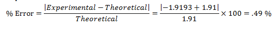
Percent error between the two values is exceptionally close to 0, thus proving that the fore of tension is equal to the force of gravity added to the force due to centripetal acceleration.
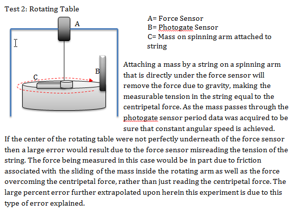
 Test 2: Rotating Table
The measurements taken from Test 2 were recorded and placed onto graph 2. The period and force were measured from 0-26 seconds, as shown in graph 2, to obtain the minimum value of force and be assured that the period was constant over the course of the trial.
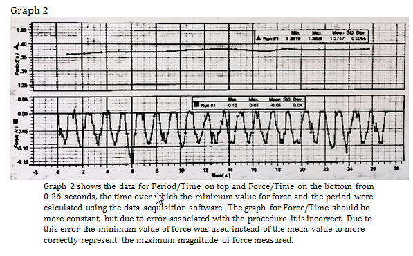
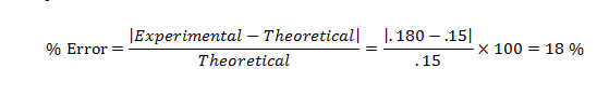
The measured minimum value for force was found to be .15N and the mean period was found to be 1.375 seconds. Using equation (10) one can calculate the expected centripetal force, or force of tension experienced by the string by using the mean period data.
Radius of the spinning circle, r= .113 m — Mass on spinning arm attached to string, m= .075 kg
![]()
There is a large percent error that corresponds to the systematic error associated with the experiment as previously highlighted in the Experimental Details. Due to not making sure that the rotating arm was precisely underneath the force sensor, the force measured was the combination of some forces and not just the isolated centripetal force.
Propagation of Error
Propagation of error associated with the two experimental procedures can be calculated from the formulas for propagation of random error. Since error in this experiment can be either positive or negative it is useful to use an error formula that examines error squared as expressed by (du)2. The formula for the propagation of random error of the formula is shown below where s is the standard deviation:
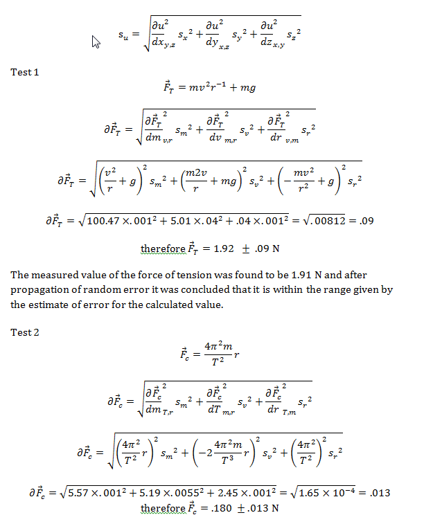
given by the estimate of error for the calculated value. This large deviation in the results is due to error associated in the experiment.
Summary of Data
Force of tension calculated from experiment 1 and centripetal force calculated from experiment 2 with propagation of error and percent error from the measured value.
|
% Error |
|||||
| Test 1 |
1.92 |
.09 |
.49 % |
||
| Test 2 |
.18 |
.013 |
18 % |
Conclusion
It was concluded that after experimentation, the procedures herein support the equations presented earlier. Two experimental conditions were measured using 1) a simple pendulum and 2) a rotating table and the force of tension exhibited on a string was measured in both cases. In the case of a simple pendulum, the force of tension is equal to the force of gravity plus the force of centripetal motion. Using Newton’s laws of motion and data collected from experimental procedures, the forces exhibited during centripetal motion were calculated and the formulae manipulated to find the error associated with the experiments conducted. In the case with a rotating table, the force due to gravity was minimized and the force of tension was only dependent upon the path of circular motion of the mass. Although a large percent error was found for Test 2, overall the procedure produced sufficient results to support the claims made before in the Introduction and Theory section.
References
[1] D.C. Ingram, Laboratory Experiments for General Physics: Experiment 5 Centripetal Force (2011)
[2] J. Walker, Fundamentals of Physics (John Wiley, New York 2011), p. 70-72
