Diffraction Patterns from Polystyrene Beads and from Breath Figures
By: Ludmila Novikova
Abstract:
Before X-ray diffraction of crystals was applied to determine the arrangement of atoms in 1913, little was known about the geometric and stereochemical shape of molecules and about the science of crystallography in general. In fact, the atomic theory of matter was not completely accepted because there was no theory available to explain the existence of compounds of the same composition (Flack, 372). X-ray crystallography presented us with methods that would allow us to strike a chosen crystal with a beam of X-rays so that we could measure and interpret the diffraction patterns that would be produced from the crystal. The calculations of the angle of diffraction, wavelength paths and distances between the atoms in the crystal are useful in determining the positions of atoms in a crystal, their chemical bonds, electron density, and much more. The resulting information is then used to analyze the structure and function of bio molecules. We can already get a sense of how important and advantageous the study of crystallography is, and one of the primary objectives in this chemistry project was to study diffraction patterns of crystals to better understand diffraction phenomena. Throughout the semester, I worked with small sizes of polystyrene beads to analyze, compare, and interpret the outcomes of the scattering and diffraction patterns given out by the crystallites. The size of the beads had to small because they would create diffraction patterns that could have defined and distant spacing lengths between “points” of the crystal. These polystyrene beads ranged from .5mm to 3 mm in diameter and they were diluted in different mixtures of water, ethanol, glycerol, cationic surfactant, and even with a small amount of potassium chloride solids. They were then delivered onto glass slides, covered with glass cover slips so that then they could be placed into an apparatus that held the slide in place. A helium-neon laser was then used to shoot a beam of emitted photons of the same wavelength (632.8nm) so that diffraction patterns could be produced. It should be noted that the monochromatic light had to pass through a magnifying lens that focused in on one sample of the microscope slide. The goal in this crystallography project was to create a monolayer of polystyrene beads on the glass slides to see hexagonal packing. Measurements of the angle of diffraction and distances between a set of “points” could then be carried out and the calculations could then be applied to make an analogous method for finding protein structures. Towards the end of this project, it was also found that diffraction patterns could also be given out by breath figures. The condensed tiny droplets of water formed an epitaxial film on the glass slides and this observation turned out to be useful because breath figures are smaller than .1mm. Overall, much was learned about the study of crystals, spectroscopy, diffraction gratings, and breath figures to come to the conclusion of how X-ray crystallography can help us study internal structure of crystalline materials.
Introduction:
Let us start off with the definition of a crystal. A crystal is a crystalline solid whose atoms are arranged in a repeating pattern. At a nano scale, the crystals’ complex arrays of atoms rarely have a perfect internal structure, and most often the crystals have misalignment of the arrangement of these atoms.
In theory, if we take a crystal (using high tech equipment) and we want to determine its crystal structure, we have to apply mathematical equations to the diffraction patterns it gives off when X-rays are shot at it. In X-ray crystallography, the X-rays are waves of electromagnetic radiation that are scattered by atoms. The X-rays essentially produce a diffraction pattern because their wavelength is typically the same order of magnitude as the spacing between the diffracting planes and the spacing between the points of the atoms. These patterns can be seen on some type of slide that shows the image of the diffraction pattern.
The diffraction pattern is produced because the electromagnetic waves from the X-rays interfere with each other constructively and destructively which results in the image we see when the X-ray light interacts with the crystallites.
When we finally determine the crystal structure of the crystal we’re studying, we can correlate its structure to the structure of bio molecules such as proteins. The applications of X-ray crystallography can help us better understand the structure of the proteins, and since “structure” of proteins is related to their “function”, we may also learn more about the function of the various proteins we might be studying.
Background Chemistry:
Crystal Structure Determination: A crystal’s structure may be determined if we take a sample of a small crystallite and measure the variations of the intensity of radiation passing through a portion of the crystal. We must then find the angle of diffraction between the diffracting planes and we must measure the path lengths of the rays.
There are many definitions for different terms when we’re discussing various locations on a crystal. Below is a list of the basic definitions applied to all crystals.
- Lattice: An infinite array of points in space. The points have identical surroundings to all other points.
- Crystal Structure: The periodic arrangement of atoms in the crystal.
- Unit Cell: The smallest component of the crystal. Many unit cells compromise the crystal.
- Asymmetric Unit: Fraction of a unit cell
As for the mathematical equations that are applied to the diffraction patterns, most of them branch off from Bragg’s Law of diffraction. The Bragg’s Law of diffraction gives the angles for coherent and incoherent scattering from a crystal lattice.
Bragg’s Law of Diffraction: nλ=2dsinθ
It is for this law that we can confirm the existence of real particles at the atomic scale. Why? Because the tiny particles we’re observing scatter light. And although white light (400-700nm) consists of waves that have different intensities, the objects that scatter this light have different scattering patters. This is important to note because tiny objects usually do not give significant scattering of the light, but if we use a beam of X-rays, which have a wavelength of 10-35nm, we’ll then be able to see the scattering pattern from those tiny molecules. This is true because the size of the tiny objects correlate to the wavelength of the X-rays. Low wavelength (like X-ray wavelength) correlates to high energy. We can conclude that a lot of energy is proportional to high frequency.
Diffraction is the interaction of radiation with matter. In this project, the “matter” refers to polystyrene crystallites and the “radiation” refers to monochromatic light from a laser.
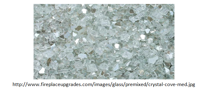
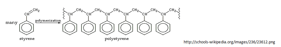
Polystyrene Beads: Beads of aromatic polymers. Polystyrene is commonly used in the industry of plastics. It is also solid at room temperature and the chemical formula is C8H8.
In this project, we are using monochromatic light because its wavelength is 632.8nm, it has a narrow frequency, and the energy levels are not strong enough to melt the polystyrene beads. Basically, if the wavelength is increased into the range of white light, we will not see any diffraction points. We must keep the wavelength 1.33 X 10⁻⁶ or lower to be able to see diffraction points. When the laser light is shot out at a crystal, the crystallites emit and absorb energy as they jump from an excited energy state to a ground state. The emitted and absorbed radiation occurs because of the interaction between the beads and the monochromatic light.
When many polystyrene beads are atop of one another, and monochromatic light is shot at the beads, the scattering pattern presents us with circular diffraction, called powder patters. These powder patterns are circular because the polystyrene beads are the same size and they’re giving out diffraction patterns in all directions. When there is a monolayer of polystyrene beads, you get a diffraction pattern. If you take a picture of this diffraction pattern, you can find the angle of diffraction using your knowledge of the wavelength of the laser, and your knowledge of the size of the polystyrene beads, and your measurements of the spacing between the “points” on the diffraction pattern.
One of the problems in X-ray crystallography, when determining crystal structure, is the issue of observing a crystal that is too small. It takes time to grow the perfect crystal and once you’ve finally chosen the crystal you’d like to study, you must keep in mind that when the crystal is placed on the goniometer head (X-ray crystallographic device), the crystal is rotated in the X-ray beam, so that it gives off diffraction patterns that reflect the radiation at different levels of absorption. This absorption depends on the path lengths of the X-rays through the crystal and it changes as the crystal is oriented. The mathematics is done through a computer programed system, but factors such as these are crucial in order to understand how the crystal structure correlated to the structure of various bimolecular chemicals.
To avoid crystallography problems in our experimentation, you must make sure to keep the different sizes of the polystyrene beads away from each other because they might mix in with each other and you will never know because the beads are tiny.
Pre-Laboratory Quiz:
1) What is a crystal?
A crystal is a crystalline solid whose atoms are arranged in a repeating pattern.
2) What is diffraction?
Diffraction is the interaction of radiation with matter
3) Why do we need to use monochromatic light when observing 1mm polystyrene beads?
We are using monochromatic light because its wavelength is 632.8nm, it has a narrow frequency, and the energy levels are not strong enough to melt the polystyrene beads
4) What would happen if we used white light to observe the diffraction patters from the polystyrene beads?
We would not see any diffraction patterns because the wavelength of the white light would be too long and it would not correlate to the size of the beads.
5) What is the name of the X-ray crystallographic device that is used to determine the crystals’ structure?
Goniometer
6) Name one problem that scientist might encounter when working with crystals?
The crystal might be too small to have its structure determined. It takes time to grow enough of the crystal for it to be observed and analyzed.
7) What is the Bragg’s law of diffraction?
nλ=2dsinθ
8) What are powder patters?
Powder patterns are circular diffraction patterns because the polystyrene beads (for example) are the same size and they’re giving out diffraction patterns in all directions.
9) What is the chemical formula for polystyrene?
C8H8
10) What is one benefit from determining the crystal structure of the crystal being studied?
We can use the crystal structure to understand the structure of proteins.
Laboratory Experiments: Flowchart of the Experiments
Section A: Powder Patterns
Section B: Diffraction Grating
Section C: .5mm Polystyrene Diffraction Pattern
Section D: 3mm Polystyrene Diffraction Pattern
Section E: Breath Figures
Section A: Powder Patterns
Goal: To recognize powder patterns and understand how and why they form.
Powder patterns are patterns of circular diffraction given out by many crystallites that are superimposed on each other, clumped together, and atop of one another.
Procedure:
1) Set up a helium-neon laser
2) Tape a magnifying lens to the opening of the laser
3) Stack 3 1X96 well-trays atop of one another 10 cm in from of the laser opening.
4) Place 4 straws into the top tray so that they can hold the glass slide. (Look at picture below)
5) Set up a white slide 3 feet away from the apparatus to look at the diffraction patterns.
6) Deliver one drop of .5mm polystyrene beads onto the glass slide and spread the beads with a brush.
7) Let the mixture dry.
8) Take the slide and place it between the 2 straws on each side.
9) Look at the slide to observe the scattering pattern.
Apparatus Diagram:
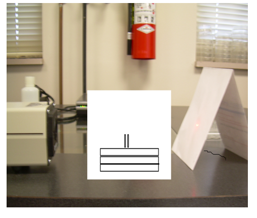
The apparatus in the middle holds the slides.
The pattern should appear to have circular concentric rings around the undiffracted beam (the most intense beam) This pattern is called a powder pattern, and you should be able to see it because the drop of the polystyrene beads from the hydrophobic solvent were not diluted in water. If the polystyrene beads were highly diluted, you would see hexagonal packing in the diffraction pattern.
Section B: Diffraction Grating
Goal: To apply Bragg’s law of diffraction to find the angle of diffraction from a diffraction grating that has 75000 grooves per cm.
A diffraction grating is a piece of a plastic slide with many tiny spaced slits in it that diffract laser beam light into an order of points that have different intensities. (Refer to picture below)
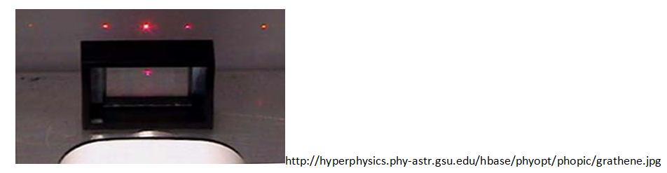
When we use diffraction gratings with a laser, we know that the points displayed are 2-dimentional. Because the points are 2-dimentional, we use the Bragg’s law of diffraction that is not 3-dimentional. This equation comes out to be nλ=dsinθ. The wavelength of the laser was 632.8nm, the distance between the grooves was 75000 grooves per cm, and the integer number was 1. If we plug this information into the equation, we can find the angle of diffraction.
Procedure:
1) Place a piece of diffraction grating 10cm away from the laser.
2) Mark the points of interaction between the laser light with the diffraction grating.
3) The mathematical procedure of finding the angle of diffraction is written out below.
The calculations should show that there was constructive interference between the grooves. The grooves allowed the light to pass through and as the light passed through, it separated between the slits. The angle of diffraction also depends on the wavelength of light. From previous experimentation, we can also conclude that the relationship between the angle of diffraction and wavelength determines the color we see.
Question to consider: If there was destructive interference between the rays, would the equation of nλ=dsinθ be true? No, the nλ would not equal dsinθ because the rays would cancel each other out.
Section C: .5mm Polystyrene Diffraction Pattern
Goal: To create a monolayer of .5mm polystyrene beads on a glass slide and prove that the wavelength of the laser correlates to the size of the polystyrene beads.
.5mm is a very small size. From the introduction and background chemistry, we may recall that is preferable to work with small crystallites because they give out a more precise image of the diffraction patterns. The beads give out “points” onto the slide whose spacing can be measured easily because it is not clumped together. The smaller the beads are, the more distant the spacing is between the points is. This is what we would like to prove in this experiment and in the next one where we will be using 3mm polystyrene beads.
Procedure:
1) Get out a clean microscope slide with a clean cover slip and set them aside.
2) .55mm polystyrene beads need to diluted in lots of water and ethanol. To prepare the mixture, you must deliver 1 drop of the beads from a pulled micropipette into a well in the 1X24 well tray.
3) You must then add 20 drops of water and 10 drops of ethanol into this tray and mix them all together.
4) Suck up the solution using a clean micropipette and deliver 1-2 drops of this solution onto the microscope slide.
5) Make a wet mount by placing the cover slip over the solution. Try to avoid any air bubbles.
6) Place the slide into the apparatus that holds microscope slides.
7) Find a monolayer on the slide
8) Observe the diffraction patterns.
9) What do you see? (If you see scattering patterns, this means that the beads are not diluted enough)
10) Mark the spots on the slide. Keep the recorded markings on the slide for further comparison with the 3mm polystyrene bead diffraction patters.
To get a defined image from the polystyrene beads, it is also useful to cut out a hole in the slide (paper) for the undiffracted beam to go through. This will allow you to see the different intensities of the various points on the image. Also, make sure to record your data immediately after you have found a clear diffraction pattern because from experimentation, it was noticed that the polystyrene beads were moved by the laser light and the beads were also melted. It is hard to avoid these problems because the magnifying glass directs a lot of energy onto a sample on the microscope slide. High energy is what is responsible for moving and melting the beads.
Section D: 3mm Polystyrene Diffraction Pattern
Goal: To compare the diffraction patterns from the 3mm polystyrene beads to the diffraction patterns from .5mm polystyrene beads.
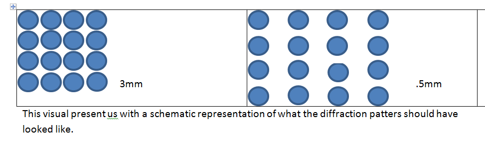
The diffraction patterns from 3mm polystyrene beads should come out to be smaller, more clumped (packed) together and the spacing between the points should be small as well. In the following experiment, we want to prove that the spacing between the crystallites can be interpreted knowing the size of the polystyrene beads. The primary objective here is to show that the bigger the polystyrene beads are, the harder it is to detect a diffraction pattern. If the beads are bigger than the wavelength of the monochromatic light, we will not be able to see the diffraction patterns at all.
Procedure:
1) Repeat everything from Section C using 3mm polystyrene beads.
2) What diffraction pattern do you see?
Compare the diffraction patterns from both experiments and explain what you would expect to see if we used .01mm polystyrene beads.
Section E: Breath Figures
Breath figures are condensed tiny droplets of water formed that form an epitaxial film on the glass slides. They are useful in our research because breath figures range from .1mm to .01mm. In theory, we may obtain diffraction patterns that have distant spacing between the water molecules. In the following experiment, we will observe breath figures.
Procedure:
1) Take a styrofoam cup and fill it with hot water of 65°C
2) Place the top lid of a petri dish onto the opening of the cup and let it sit there until a cloud forms underneath the lid
3) Place the lid back onto the bottom half of the petri dish
4) Allow laser light to pass through a sample of the cloud
5) Observe and record diffraction patterns.
The diffraction patterns should come out to be well defined because the size of the water droplets ranges from .1mm to .01mm.
To continue on with these experiments, we can observe diffraction patterns from various chemicals like the interaction between HCl and NH3. As a chemical front is formed off the surface of the NH3 drop, smoke will fill the petri dish and the NH4Cl particles will form small solid crystallites that will too give off diffraction patterns.
6) Take a clean petri dish and place one drop of NH3 on the top and one drop of the HCl onto the bottom half of the petri dish
7) Close petri dish
8) Allow the smoke to fill the petri dish
9) Shoot laser light through the petri dish
10) Compare the diffraction patterns given off by HCl and NH3 and water molecules from water vapour.
An advantage of studying diffraction patterns from breath figures rather than from polystyrene beads is that it is cheaper. The price to gather the apparatus materials for polystyrene beads came out to be over a $100. Thanks to Dr. Thompson, I was able to study diffraction patterns through the use of these micron sized polystyrene beads.
Bibliography:
Works Cited
“Bragg’s Law.” Wikipedia, the Free Encyclopedia. Web. Feb. 2011. <http://en.wikipedia.org/wiki/Bragg’s_law>.
Clegg, William. Crystal Structure Determination. Oxford: Oxford UP, 1998. Print.
“Crystallography.” Wikipedia, the Free Encyclopedia. Web. 28 Jan. 2011. <http://en.wikipedia.org/wiki/Crystallography>.
“Epitaxy.” Wikipedia, the Free Encyclopedia. Web. 18 Apr. 2011. <http://en.wikipedia.org/wiki/Epitaxy>.
Feynman, Richard P. QED: the Strange Theory of Light and Matter. Princeton, NJ: Princeton UP, 1985. Print.
Flack, H. D. “Louis Pasteur’s Discovery of Molecular Chirality and Spontaneous Resolution in 1848, Together with a Complete Review of His Crystallographic and Chemical Work.” Web. Jan. 2011. <http://library.epfl.ch/en/periodicals/?recId=12869839>.
Taylor, Charles Alfred. Images: a Unified View of Diffraction and Image Formation with All Kinds of Radiation. London: Wykeham Publications, 1978. Print.
Thompson, Stephen. Chemtrek: Small-scale Experiments for General Chemistry. Englewood Cliffs, NJ.: Prentice Hall, 1989. Print.
