The Resultant of Multiple Forces
By: Diane Krehbiel
Goal:
The goal of this experiment is to use a force table to see the effects of adding vectors. Multiple forces will be attached to a center point. Force components will be added and subtracted both graphically and trigonometrically.
Introduction:
Vectors are quantities measured in both magnitude and direction. They are usually represented by an arrow. Two vectors are considered equal despite of the initial points as long as the vectors have the same magnitude and direction (“Vectors”). Vectors can be added by breaking them down into their x and y components and adding those separately. The magnitudes from the x and y components can be used to find the angle of the resultant vector. After adding the vectors, the net force can be determined. An object is at equilibrium when the forces are balanced and Fnet = 0 N (“Forces”).
In this experiment, a force table will be used to study the interactions between vectors and their resulting forces. Two or more forces acting on an object that pass through a center point are called concurrent forces. We will be studying three different forces in this experiment. The sum of the two forces or vectors is called the resultant force. The third vector equal to the resultant is called the equilibrant. The three forces in this experiment are all in the same plane and therefore are coplanar. Throughout the trials in this experiment, 2 masses will remain the same while the mass of a third force will be altered. The angle must be found in order for the forces to remain in equilibrium. The ring at the center of the table should be balanced and centered. The resultant value can be calculated and also the equilibrant vector. The percent difference can be calculated from the results obtained and what the actual results should be.
Experimental:
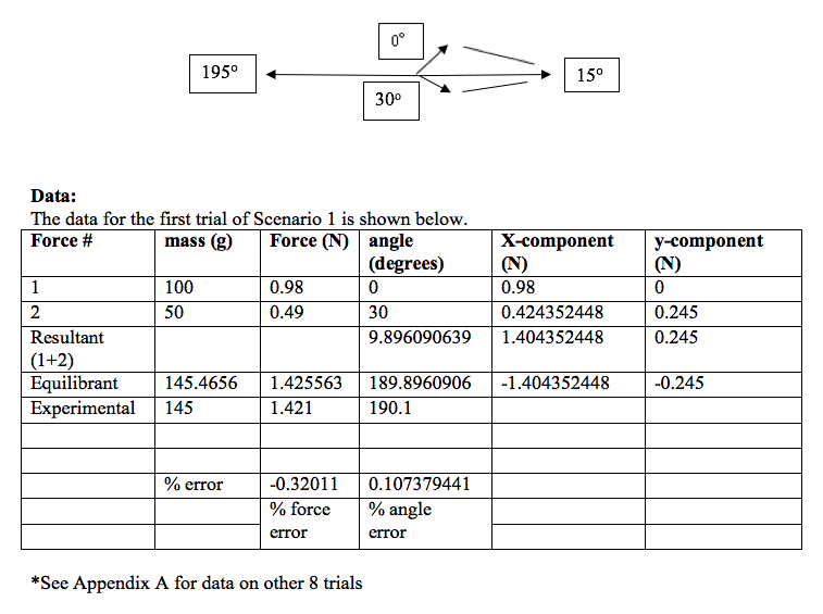
In the first scenario of this experiment, set up the force table using one angle at 0° and the other at 30°. Add mass to the hanger at 0° so that the total is 100 grams and to the 30° hanger so the total mass is 50 grams. On the third hanger, add mass so that the ring is centered in the middle. When the correct mass is obtained, record the angle at which the vector is positioned. The resultant of the forces can then be calculated and also the percent difference from the actual value. Instead of writing out the entire table in the lab notebook, it is simpler to record data in an excel spreadsheet and calculate the data using that. But be sure mass, force, and angles are clearly recorded in notebook as well as percent error.
For the next two trials, add different amounts of mass to the hanger at the 30° mark. Repeat the step in finding how much mass is needed on the third vector in order for the forces to reach equilibrium. Record data in notebook.
In the second scenario of the experiment, set up one of the hangers at 0° with a mass of 100 grams. This time, instead of the second hanger at 30°, set it up at 90° with a mass of 50 grams total. Repeat the same steps in finding the equilibrium by moving the third force to the correct angle and mass. For the next two trials in this section, add different masses to the 90° angle and discover the correct angles. Record data in notebook.
The third scenario in the experiment will again begin with one force on the 0° mark and 100 grams as its mass. Place the second one at 135° with a mass of 300 grams on it. Adjust the mass and angle of the third force until there is a net force of 0 and equilibrium is reached. Add mass to the angle 135° and repeat the trial twice more. Make sure data is recorded in notebook. After each trial, sketch a picture of each vector at the correct angles and the forces at the correct length. Only one has to be exactly measured with a protractor. The following trials can just be sketched. Below is an overhead view of what one trial looked like in our experiment. The vector pointing to the 15° is the imaginary vector representing the resultant force.
Calculations:
Force = ma
Force = 0.100 kg x 9.8 m/s2
Force = 0.98 N
Force = X component = cos(angle) x force
X = cos(0) x .98 N
X = 1 x .98 N
X = 0.98 N
Y component = sin(angle) x force
Y = sin(0) x .98 N
Y = 0 x .98 N
Y = 0 N
Resultant Angle = tan-1(Ry/Rx)
Angle = tan-1(0.245/1.404)
Angle = 9.90o
Equilibrant Force = √(x2 + y2)
Force = √(0.2452 + 1.4042)
Force = 1.43 N
% Error = [(Actual – Experimental) / Actual] x 100%
% Error = [(1.4256 – 1.421) / 1.4256] x 100%
% Error = 0.320%
*Repeat same calculations for all trials
Results:
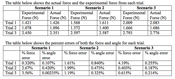
Scenario 1
Average % error (force) = 2.18%
Average % error (angle) = 0.176%
Scenario 2
Average % error (force) = 1.60%
Average % error (angle) = 0.546%
Scenario 3
Average % error (force) = 1.74%
Average % error (angle) = 0.219%
Discussion:
The forces and angles discovered in this experiment were all close to accurate. The experimental vectors found in the experiment were all very close to the actual equilibrant vector. The trial that seemed the most accurate in both angle and force was the first trial from the first scenario. The percent error for the force was 0.320%, and the percent error for the angle was 0.107%. This trial matched up best with the calculated equilibrant. All of our values seemed accurate with the percent error for all scenarios under 5%. The small discrepancies between actual and theoretical values could be caused because of different reasons. One could be that there was not a perfectly frictionless surface between the pulley and the string. This could have caused the vectors to look equal even though friction was playing a part in that and not taken into account when calculating values. The factor of friction was small enough though to not make a huge difference. Another reason for error could come from the measurement of the angles. The third angle is just estimated by what the human eye can see. This could cause some error in measurements.
In this experiment, there is not a way to arrange two vectors so that a third will not be able to cancel them out. Even if two vectors were placed at the exact same angle, a third one would be able to cancel them out directly opposite of the other two vectors. It would be difficult to perform this on the force table because two strings would have to go over the same pulley, but it could be accomplished. I like the method of finding vectors graphically. It does take more time to perform it this way rather than component analysis, but I understand the experiment better when I see it visually. Drawing the vectors graphically is easier for me to understand. When calculating the vectors, we knew if the angle was going to be between 0 and 180° or 180 and 360°. This was because we knew that the vector would like directly opposite of the resultant and the resultant was between the original two vectors. Therefore we could estimate where the third vector would lie. Overall this experiment was successful and accurate results were obtained.
Conclusions:
In this lab, the resultant of multiple forces was studied along with the angles of different vectors. Experimental values of force and angle were discovered and compared to what the actual values should be. The most accurate trial was the very first one with percent errors for the force and angle at 0.320% and 0.107%. All values had percent errors less than 5%
Works Cited
“Addition of Forces.” The Physics Classroom, n.d. Web. 16 Sept. 2013.
“Vectors.” Department of Physics, University of Guelph, n.d. Web. 15 Sept. 2013.
