

Centripetal Force Experiment: Whirling Stoppers, Spinning Platforms and Straight-Line Graphs
Tie a rubber stopper to a string, whirl it overhead, and you can feel the string pulling on your hand. Spin it faster and the pull grows. The centripetal force experiment turns that feeling into numbers. It measures a mass, a radius and a period, then checks whether the force needed to keep something moving in a circle matches what Newton’s second law predicts.
What centripetal force is
An object moving in a circle at constant speed is still accelerating, because its direction keeps changing. OpenStax’s University Physics gives that acceleration as ac = v2/r, pointing toward the center of the circle, or ac = rω2 if you know the angular velocity. Multiply by mass and you get the force:
Fc = mv2/r = mrω2
The key idea is that centripetal force is not a new kind of force. In the textbook’s words, “Any net force causing uniform circular motion is called a centripetal force.” Its examples range from the tension in a tether-ball rope to Earth’s gravity on the Moon and a banked road’s push on a car. In every lab version, the job is to identify which real force is doing the pulling, and then measure it.
The whirling-stopper setup
A Boston University course handout describes the classic version: a rubber stopper on a nylon string, threaded through a glass tube, with steel washers hanging from a paper clip at the bottom. You hold the tube and swing the stopper in a horizontal circle, adjusting the speed until the washers neither rise nor fall.
When the washers hang still, the tension in the string equals their weight, FT = mwg. That same tension, passed through the tube, is what holds the stopper on its circle. The handout writes the speed as circumference over period, v = 2πr/T, so the acceleration becomes 4π2r/T2. It suggests a radius of about 20 cm and an ink mark on the string at the bottom of the tube; if the mark creeps, the orbit isn’t steady.
An introductory mechanics procedure hosted on WebAssign varies the hanging mass and has students plot the hanging weight against the calculated acceleration; the slope gives the stopper’s mass.
The rotating-platform setup
The second classic apparatus replaces your arm with a spinning shaft. In the University of Massachusetts Amherst Physics 183 manual, a plumb bob hangs from a cross arm on a vertical shaft. A horizontal spring connects it to the shaft, and a pointer below marks the target radius.
At rest, you first add mass to a pan hung over a pulley until the bob sits over the pointer; that weight equals the spring force at that radius. Then you remove the string, spin the shaft until the bob passes over the pointer, and time several revolutions. The spring now supplies a centripetal force you have already measured.
Odinity’s sample centripetal force lab report used a sensor version of this idea. A rotating table carried a 0.075 kg mass at 0.113 m, and a force sensor and photogate recorded force and period. The calculated force came out 18% away from the measured one. The author traced that to the rotating arm not sitting “precisely underneath the force sensor.”
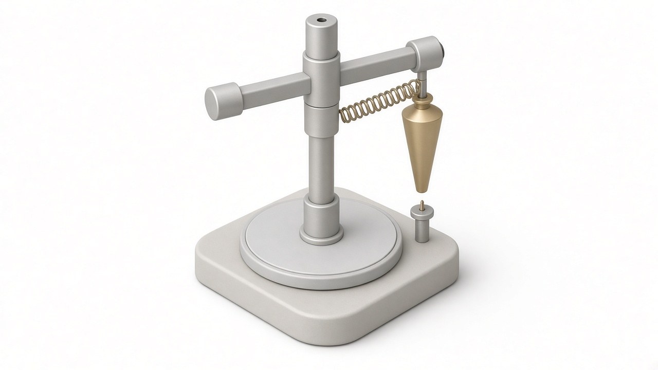
Illustration of a rotating-platform centripetal force apparatus (artist’s impression).
Why centripetal force experiment graphs are straight lines
The point of the centripetal force experiment is a pattern, not one number: both setups can be run so the data should fall on a straight line, as the UMass and WebAssign procedures ask.
Force against acceleration (or v2/r). Since F = m(v2/r), plotting force against v2/r should give a straight line through the origin with slope equal to the moving mass. The UMass manual asks for exactly this: “each of the two F vs. a graphs should be a straight line through the origin with a slope equal to the corresponding plumb bob mass.” It repeats the test with an extra 0.1 kg on the bob, so a second, steeper line should appear.
Period squared against string length. In the stopper version, the BU handout reduces everything to
ms4π2L/T2 = mwg
Here ms is the stopper mass and L is the string length from the top of the tube to the stopper. Rearranged, T2 = (4π2ms/mwg)L. Hold the hanging weight fixed and change the length, and T2 against L should be a straight line through the origin. (That is my rearrangement of the handout’s equation.) Odinity’s least-squares spring constant lab shows the same fitting approach on a Hooke’s law graph.
Where the errors come from
The string isn’t horizontal. The stopper has weight, so its string droops below the horizontal. The BU handout handles this neatly: only FT cos θ pulls the stopper inward, but the true radius is r = L cos θ, so the cos θ cancels and you are left with the length L along the string. The practical lesson is to measure along the string, from tube to stopper, rather than mixing a horizontal radius with a horizontal-string assumption. Odinity’s resultant of multiple forces lab covers the component idea behind this.
Timing. The period enters squared, which magnifies timing error. The UMass manual spells it out: “A 1% change in r results in a 1% change in a, but a 1% change in T results in a 2% change in a.” That’s why procedures time many revolutions and divide. BU suggests about 20 revolutions, and the WebAssign procedure uses 10, “done to minimize the effect of measurement uncertainty.”
Friction at the tube. Every stopper calculation above assumes the hanging weight equals the tension at the stopper. That’s only true if the string slides freely over the tube’s rim. A Case Western Reserve University demonstration page warns that “the friction of a string going over the edge of a glass tube is not highly reproducible.” It treats its own setup as mainly qualitative. Labs fight back with hardware: the WebAssign procedure’s steel tube has a Teflon plug “designed to reduce friction.” The BU handout states its assumption openly: “Neglect all frictional forces and air resistance.”
Alignment and a wandering hand. On a platform, a misaligned sensor adds stray forces, as the Odinity report concluded. By hand, BU’s advice is “Do not move the hand too much while swinging the stopper.”
Centrifugal force: why it isn’t a real outward force
“Centrifugal force” is the usual explanation for the pull. OpenStax’s University Physics is blunt about it: “Centrifugal force is a commonly used term, but it does not actually exist.” In an inertial frame such as the lab floor, nothing pushes the stopper outward. The string pulls it inward. If the string snaps, the BU handout notes, the stopper “will move in a straight line in accordance with Newton’s first law.” It does not fly straight outward from the center.
The outward feeling comes from your point of view. OpenStax’s College Physics explains that in a rotating, non-inertial frame, like a merry-go-round or a turning car, you can describe motion using a fictitious force named centrifugal force, “not to be confused with centripetal force.” It’s a bookkeeping term for a spinning observer, with no physical source the way tension or gravity has.
Real-world examples
Centrifuges. OpenStax’s College Physics says centrifuges “use inertia to perform their task.” Spinning fast speeds up sedimentation, used to separate cells, viruses and macromolecules such as DNA and protein. Its worked example finds that a point 7.50 cm from the axis of an ultracentrifuge spinning at 7.50 × 10⁴ rev/min has an acceleration of 4.63 × 10⁶ m/s2, “472,000 times as strong as g.”
Banked curves. Tilt a road, and part of the normal force points toward the center of the turn. OpenStax’s University Physics derives the ideal banking angle, where no friction is needed at all, as tan θ = v2/(rg). It notes that “θ does not depend on the mass of the vehicle.” Its example: a curve of 100.0 m radius banked at 31.0° has an ideal frictionless speed of about 24.3 m/s, roughly 87.5 km/h.
What’s settled and what’s a rule of thumb
Settled:
- Circular motion at constant speed needs a net inward force of mv2/r.
- That force is always supplied by something real, such as tension, a spring, friction, gravity or a normal force.
- Centrifugal force appears only as a fictitious force in a rotating frame.
Rules of thumb (lab practice):
- timing 5 to 20 revolutions, with a radius of about 20 cm and an ink mark to hold it
- treating the hanging weight as exactly equal to the string tension, the weakest link, because tube friction is real and not very repeatable
Safety note: a whirling stopper is a small but real hazard. The BU handout’s instruction is simply: “Wear goggles so that the stopper does not hit anyone in the eye.”