
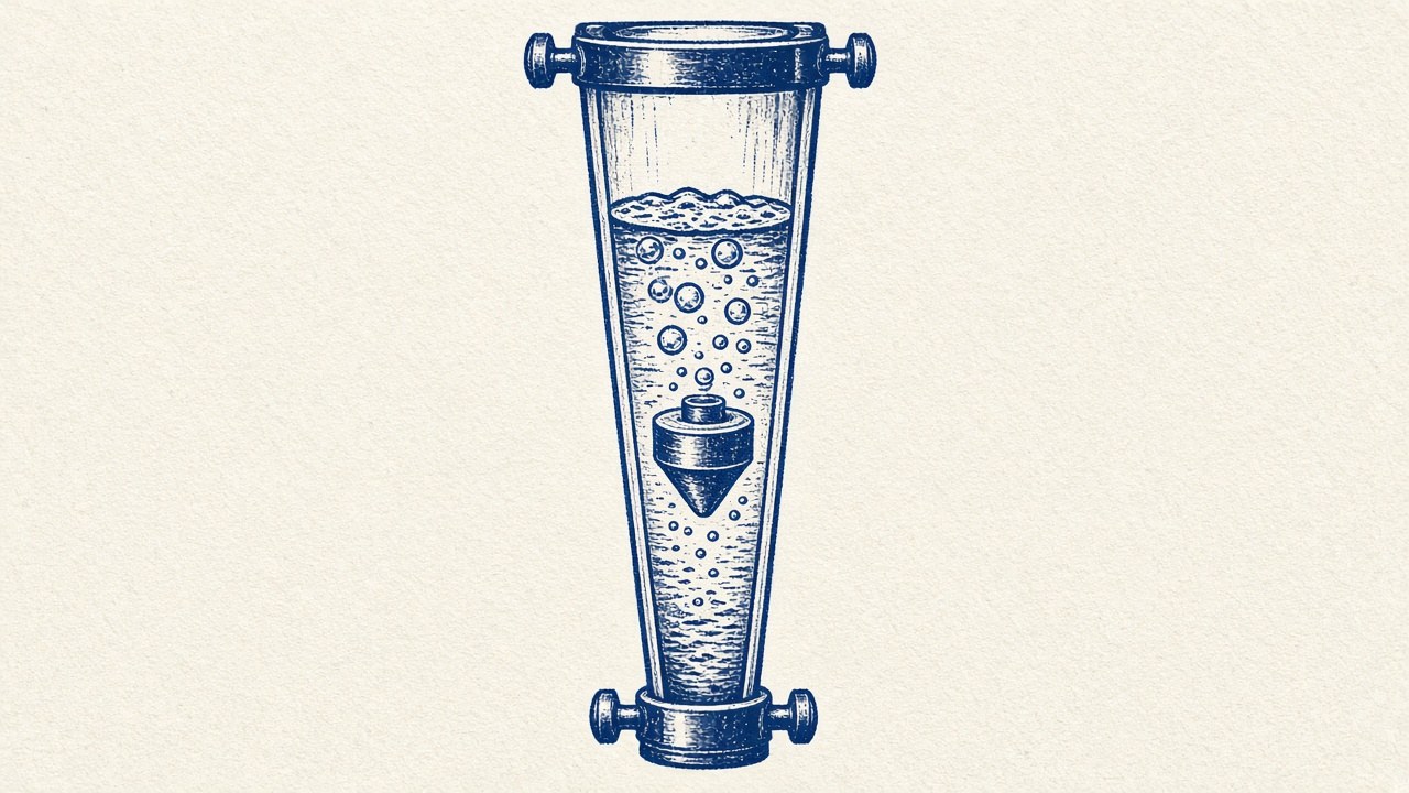
Rotameter Calibration: How a Float in a Tapered Tube Measures Flow
A rotameter is one of the few instruments you can read from across a room: a float hangs in a glass tube, and the higher it sits, the more fluid is flowing. It needs no power and has almost no moving parts. But that simple scale is only correct for one fluid, at one set of conditions, held one particular way. Rotameter calibration is how you find out what the float position really means, and how far you can trust it when conditions change.
How a variable-area flowmeter works
An instrumentation note by Andrew Mosedale at Texas Tech University gives the basic layout. A rotameter is “a vertical, variable-area tube, small at the bottom and large at the top.” Flow enters at the bottom, passes up around a float, and leaves at the top.
The float settles where three forces balance:
- its weight, pulling down
- buoyancy from the displaced fluid, pushing up
- drag from the fluid rushing past it, pushing up
Odinity’s flow meter calibration lab report describes the same picture: a float “pushed up by the drag force of the flow and pulled down by gravity.”
The taper is the clever part. Weight and buoyancy don’t change with flow, so a balanced float needs a fixed drag, and that means a fixed fluid speed past the float. Mosedale’s analysis shows there is “a unique velocity” that balances the float for a given meter and fluid, “whether the flow rate is high or low.” More flow can only be carried at that speed through a bigger gap. So the float rises to where the annular gap between float and tube is wider.
Volumetric flow rate equals that fixed velocity times the annular area. Because the area grows with height, each float position corresponds to one flow rate. Course notes for ME 3264, an applied measurements lab at the University of Connecticut, add that manufacturers shape the tube so float position and flow rate are close to linear. The calibration is then written Q = K1 + K2x, with the constants found by calibration.
Why density and viscosity change the reading
Every term in the force balance involves the fluid. Buoyancy depends on fluid density, and so does drag, along with the square of velocity. Mosedale’s rule of thumb follows from the algebra: “If a more dense and a less dense fluid pass through identical rotameters at identical volume flow rates, the float will sit higher in the more dense fluid.” A denser fluid needs a lower speed to make the same drag, so the float has to rise to a wider part of the tube.
Viscosity enters through the drag coefficient, which depends on the flow regime. Mosedale notes that the drag coefficient “might not be truly constant.” It can be treated as constant only over a narrow Reynolds-number range.
The US National Bureau of Standards (now NIST) studied this directly in a 1951 Journal of Research paper on float-type flowmeters, prompted by aircraft fuel metering. The researchers found that at a fixed float position, two liquids with densities of 0.6 and 0.8 g/cm³ and the same viscosity gave actual flows differing “by about 15 percent.”
They also found that raising viscosity shifts the reading in the opposite direction from raising density. For hydrocarbons, a temperature change usually moves density and viscosity together. The paper says the two errors “will normally be of opposite sign,” so they partly cancel, though only partly. That’s why a scale printed for water or air can’t simply be trusted for another fluid.
How rotameter calibration is done
Calibrating a rotameter means comparing its readings with an independent measurement of how much fluid actually passed through in a known time. There are three common ways to make that measurement.
Bucket and stopwatch. The ME 3264 hydraulic bench uses a volumetric version. A stopwatch times how long the water level in a graduated reservoir takes to rise between marks, and Q = V/Δt. Michigan Technological University’s transport lab, and Odinity’s report from it, use a “pail-and-scale” version:
- Set the rotameter with a needle valve.
- Divert the water into a tank on an electronic scale while starting a stopwatch.
- Collect for about a minute.
- Record the mass and the water temperature.
Mass flow becomes volumetric flow through the density of water. In the Odinity report, the students worked through rotameter settings from 20% to 70% and fitted calibration lines for three pipe sizes. The slopes were 0.0494, 0.0482 and 0.0492, so pipe diameter made “barely any” difference.
Gravimetric reference standards. National laboratories do the same thing at much higher precision. NIST’s Water Flow Calibration Facility uses the static gravimetric method:
- A diverter switches the flow into a collection tank while starting a timer, then switches it back.
- The collected water is weighed, with corrections for air buoyancy and water temperature.
For its 3700 kg tank, NIST’s Special Publication 250-73 reports an expanded uncertainty of 0.033% when a full tank is weighed. It lists the largest source of uncertainty as “the measurement of the mass of water collected.” The 1951 NBS work used both approaches: volumetric flasks for smaller flows, and later a gravimetric stand with automatic timing.
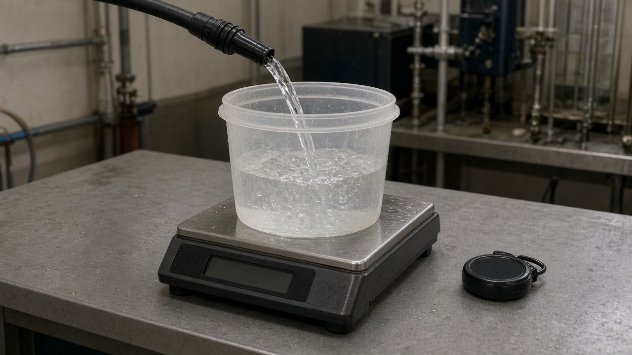
Illustration of a pail-and-scale flow check on a lab bench (artist’s impression).
Correction factors for a different fluid. When a meter calibrated for one gas is used at other conditions, the density dependence gives a square-root correction. Mosedale works through air at 13 psia and 75 °F on a meter scaled for standard air. The actual flow is Qindicated × √(ρstandard/ρactual), about 1.068 times the reading. For propane on an air-scaled meter, the molecular weight ratio alone gives a factor of about 0.81, because propane is denser. PubChem lists propane as an extremely flammable gas that contains gas under pressure (H220, H280); that line is a density-correction example only — the calibration procedures above use water.
These corrections only fix density. The NBS paper’s approach to viscosity is to calibrate the meter with a few fluids of known density and viscosity. That allows corrections for any fluid whose properties fall within that range, and the corrected values were “always within one-quarter percent of the true values of flow.”
Sources of error
- Parallax and the reading point. ISA’s recommended practice RP16.5 for glass-tube rotameters says plumb-bob floats and most other shapes are read at “the largest uppermost diameter,” while ball floats are read at the middle. Reading a different edge, or reading from above or below eye level, gives a consistent offset.
- Float bounce. In gas service, RP16.5 puts the throttling valve downstream of the meter, within a set distance, to reduce or eliminate what it calls float bounce. Michigan Tech’s procedure also warns that trapped air “can cause the rotameter float to move rapidly.” A bobbing float has no single reading, and averaging by eye adds error.
- Temperature. Temperature changes density and viscosity, and so the reading. The NBS researchers held the inlet fluid within ±1 °F, and the Michigan Tech and Odinity procedures record water temperature at each point. NIST corrects for temperature even in its reference standard.
- Not vertical. RP16.5 states that “the rotameter must be installed in a vertical position,” with piping supported so no stress reaches the meter. The whole force balance assumes gravity acts along the tube’s axis.
- Range. Accuracy is usually quoted as a percentage of full scale. Mosedale gives the example of a meter rated at 3% of full scale: the absolute uncertainty is the same everywhere on the scale, so readings near the bottom are much less accurate in percentage terms.
How rotameters compare with other flowmeters
The ME 3264 notes compare the rotameter with two other common meters:
- Rotameter: about ±3% of full scale. It’s cheap, readable at a glance and needs no power, as the Odinity report notes. It has to be read by eye unless fitted with extras.
- Venturi meter: flow follows Q = C√Δp. That requires a pressure measurement and a discharge coefficient to account for viscous effects.
- Turbine meter: flow is the meter’s frequency output times a K-factor, typically ±3% of reading. A percentage-of-reading spec holds up better at low flow.
Odinity’s report calibrated a rotameter and an orifice meter side by side; the orifice needed a pressure-drop meter and its own calibration curve. Related Odinity labs cover measuring viscosity and a peristaltic pump calibration that uses the same mass-to-volume logic as pail-and-scale.
What’s settled, and what’s a rule of thumb
The physics is settled. A rotameter balances weight, buoyancy and drag, so its scale depends on the fluid’s density and, through drag, its viscosity. Calibration against a mass or volume collected over a measured time is the standard way to tie float height to flow.
The rules of thumb are about practice:
- Use the square-root density correction for gases.
- Read at the float’s widest edge.
- Keep the tube plumb.
- Size the meter so you work near the top of its range.
The more the working fluid differs from the calibration fluid, the less any printed correction can be trusted. The safest course is to calibrate with the fluid you’ll actually measure.